
Soldering is an essential practice in any maker’s repertoire.
The first time I soldered was also around the first time I could hold a pencil. However, I have only recently (almost two decades later), learned how to solder properly.
“Good” soldering practices are an extensive subject, but a few key components are essential in almost every technique. One of those components is flux. Flux is a chemical used to clean the metal surfaces that you are applying solder to. The flux itself is not “activated” until you apply heat, whereupon the flux will remove oxidation on the metal surfaces to be joined, allowing molten solder in the vicinity to attach to (a process known as “wetting”) the metal surfaces being connected.

The smoke that arises from soldering is not from the solder metal itself, but from the flux. Since flux is essential in achieving strong solder joints, there is no way around producing smoke when soldering. This is why fume extraction is necessary when you solder on a regular basis; inhaling any kind of smoke can only be a detriment to your health!
There are many styles of smoke extractor, each with its own tradeoff between physical size, filtering performance, and overall ‘handiness’ when setting up and using.
The most common types of fume extractors are no more than an AC muffin fan with a piece of activated charcoal stuck on one side or the other.
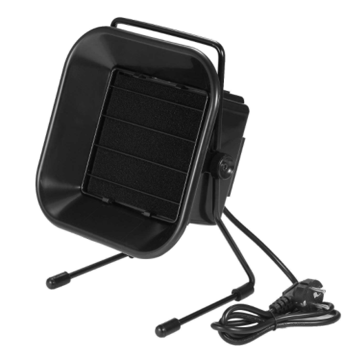
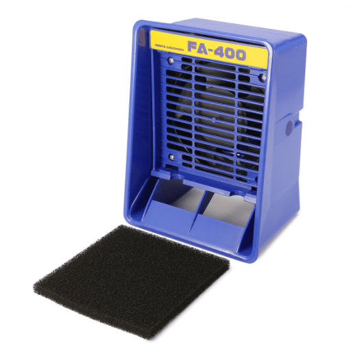
As the old adage goes, you get what you pay for. Sure, the fan might pull fumes away initially, but that scrawny piece of “activated charcoal” doesn’t do much in terms of actually removing the smoke particles from the air. You may notice that your room still reeks of solder smoke, no matter how aggressively the fan sucks up solder fumes off of the work at hand.
In a more professional setting (and where labor laws are actually observed), solder fume extractors are large boxes positioned on the floor, with ducts running up to the operator’s work area.

Of course, this style of extractor is usually equipped with several stages of filtration down to the submicron level, meaning it does a good job of actually capturing smoke and the pollutants you want to avoid breathing. The downside is also obvious; its a huge box that takes up lots of floor space.
So, is it possible to combine the best of both worlds? Why can’t we have a machine that actually filters smoke, but isn’t a huge metal box that rolls around on the floor?
There are a few attempts at such a product on the commercial market, but they still required too many compromises to use. Ideally, I wanted a fume extractor with the following qualities:
- Bench-top (footprint < 1 square foot, shallow depth facing the operator)
- Multi-stage filtration using easy to find, off the shelf filters
- > 300 CFM airflow
- Fully adjustable speed
- Semi-rigid overhead duct
So what do you do when nothing on the market meets your demands? You whip open your favorite CAD program and get to work on a new design!


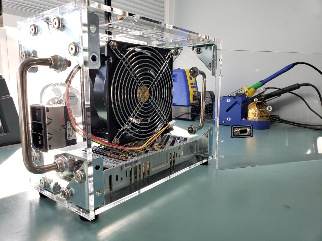
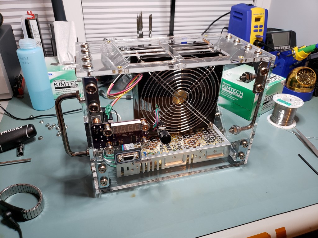
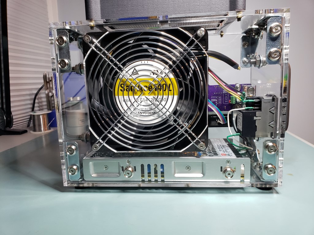
My design began around a fan and power supply combination I already had in my parts bin. The fan is a San Ace 9LG1412P5G001, which is a 140x51mm axial fan with a max airflow of 318 CFM. Static pressure is also decent at 2.63 inches of water, meaning that it should be able to pull air through a respectable filter. The power supply is a Mean-Well RSP-150-12, which is a quality 12 volt AC-DC supply with plenty of overhead for the 62 watt rated fan.
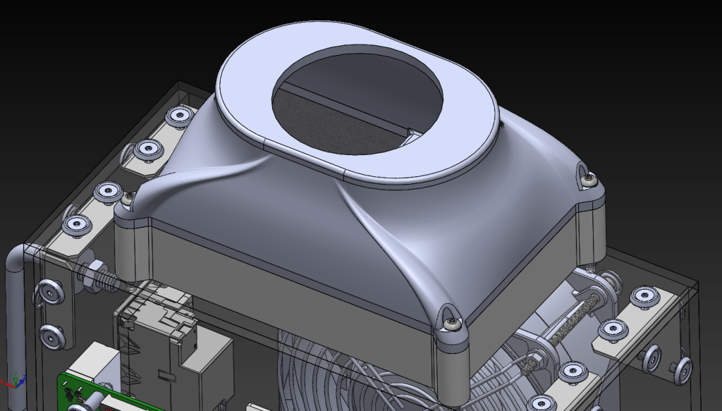
The design intent is focused on keeping the box as compact as possible. There is not a lot of wasted space between the fan and the power supply. This is also possible because the filters are housed in a separate compartment.
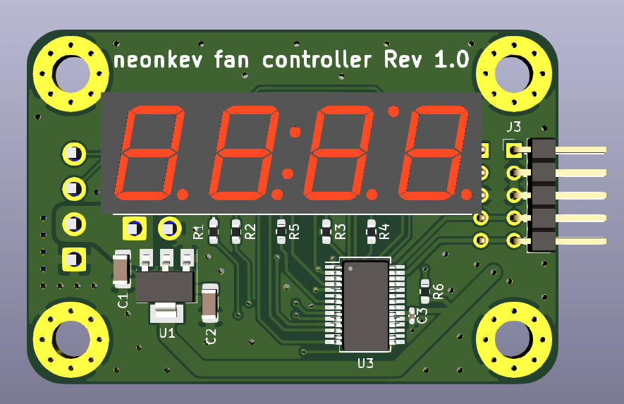
With my new and improving skills in the realm of embedded design, I opted to take my fan controller to the next level. Inspired by the simplicity and ease of use of the DIY Weller station project I built earlier, I designed my own board using the same PIC16F1788, with the intention of being able to generate PWM to control the fan and also display the fan speed in RPM. This project will mark my first venture into PIC territory! My thanks to Jaakko, the designer of the DIY Weller station, for his support in helping me to solve fundamental firmware challenges I had when getting started.

All of the fasteners and corner brackets are off the shelf items from McMaster Carr. The panels are laser cut 5mm thick acrylic. Only the filter box and plenum are 3D printed parts. These were designed to accommodate the Hakko C1571 duct kit and an off the shelf HEPA filter: Sears Kenmore EF-1, Part #86889.

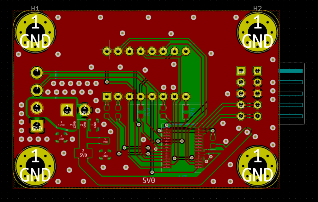
While the laser cut panels and 3D printed bits were on order, I began with fabbing up the first revision of the controller. Being that this my first time using PIC, I knew the learning curve was going to steep!
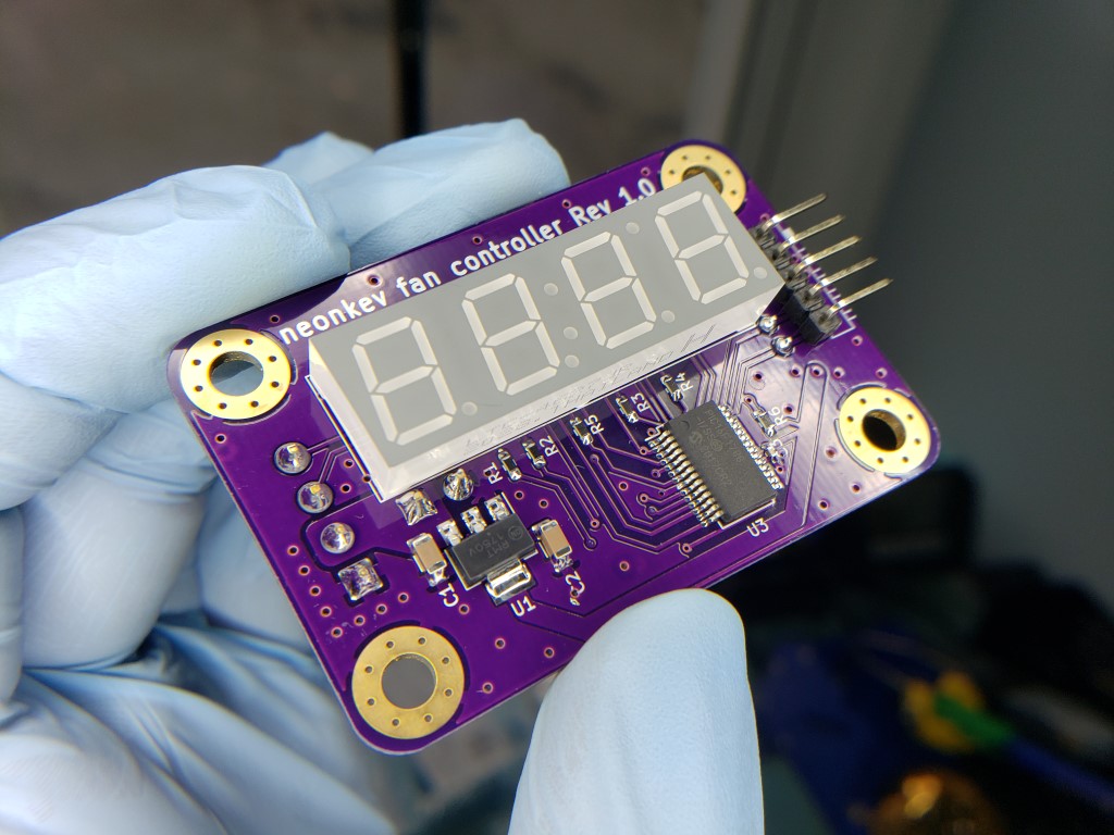
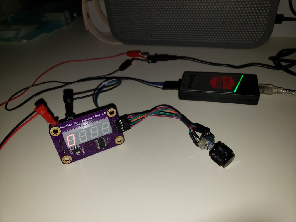
Using MPLAB X IDE 5.40 and Microchip’s free XC8 compiler, I spent many hours with the Rev 1 board to get various bits working; multiplexing the common anode display, rotary encoder software debouncing, learning about PIC ISRs, using the compare-capture (CCP) modules to generate PWM and use hardware timers… this project presented a healthy number of challenges for a first go at 8 bit PICs.
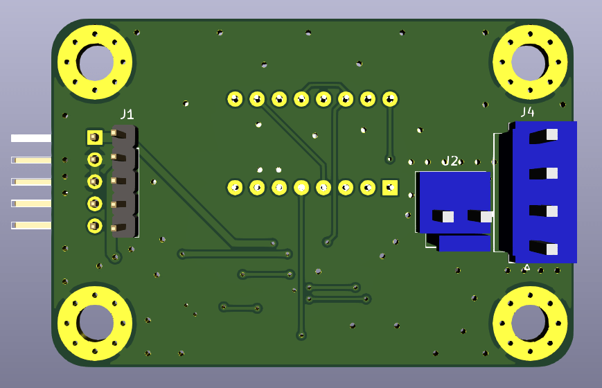
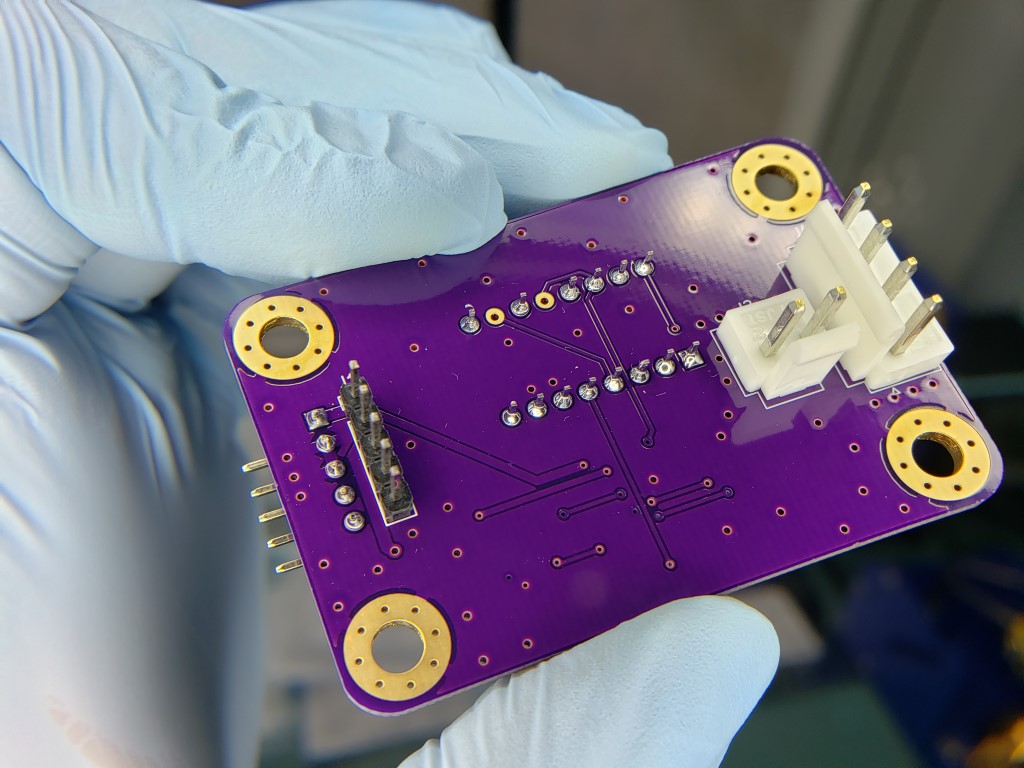
In order to use the compare capture modules (CCP) for both generating PWM to control the fan and counting the period of the fan tachometer input, I needed to alter the pinout of the fan connector. While I was designing Rev 2, I also opted to add a relay for turning the fan power on and off; some PWM fans will turn off at low duty cycle, but others do not. The relay gives the operator full control over any fan without having to turn the main DC supply on/off.
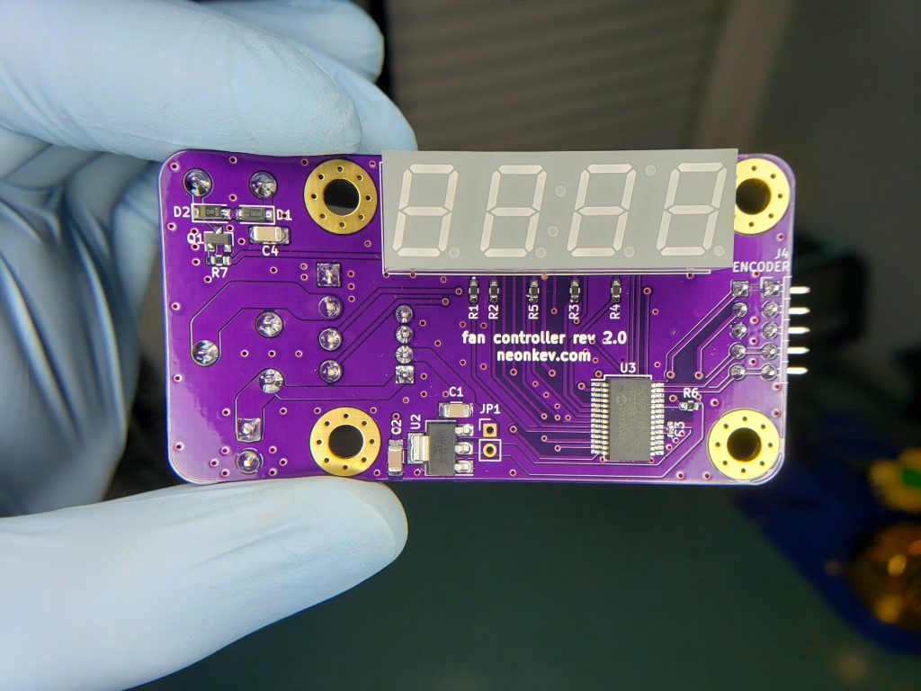

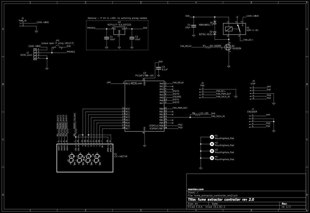
You can grab the design files if you would like to have a go at building the Rev 2 board as seen here, or designing your own 16F1788 based PCB for any fan control needs. Of course, the information and files provided are for recreational (non-commercial) use only; no guarantees are expressed or implied.
Google Drive – fan controller rev 2 gerbers, BOM, schematic, firmware
Around the same time that I was developing firmware on Rev 2, the 3D printed parts and the laser cut acrylic arrived.


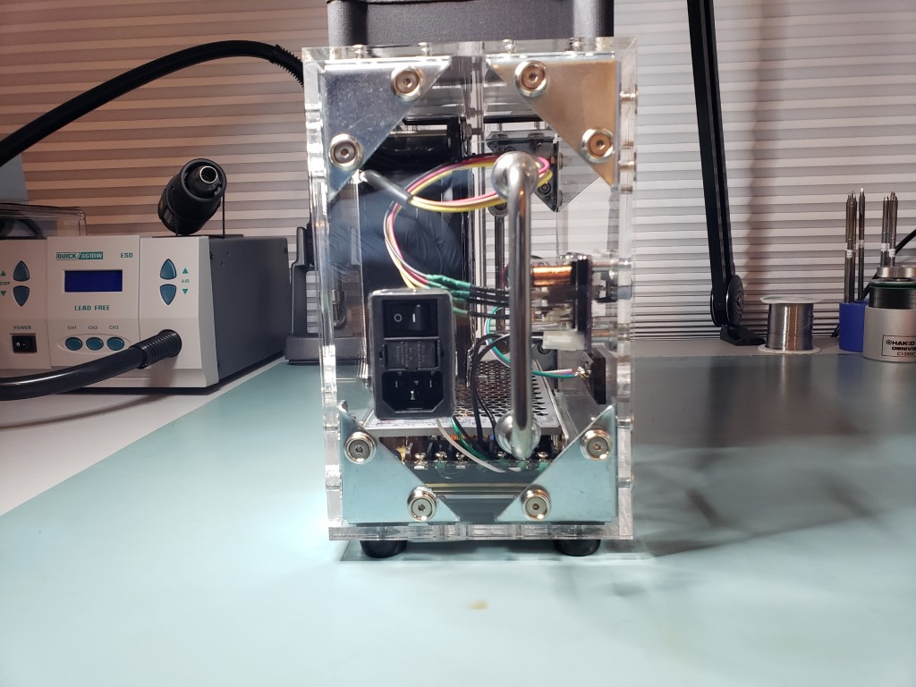
Assembly of the enclosure was a bit tricky. No adhesives or acrylic cement is used to adjoin the panels; the box is held together with fasteners alone. I opted to do this since this is the very first physical manifestation of this project, and did not want to scrap the entire thing if I needed to make a change. I did use carefully (syringe) applied JB weld to secure the mains power receptacle into place, as well as tacking the nuts for the top panel to the top four corner brackets (or else it would be impossible to put the last panel on and hold the nuts from inside the box!).
Fortunately, the tolerances on the laser cut and 3D printed parts are very tight. This means that gaps around the edges of the panels are minimal, and I did not have to grind or drill any new holes to get the fastener holes lined up. I used a syringe to apply a small amount of neutral cure Dow 737 silicone around the edges to get an airtight seal. If I ever need to open the box up for servicing, the top panel is the designated “service entrance”, as you can just barely squeeze your hand in from this direction to undo any connectors or nuts.
After the firmware on Rev 2 had reached a satisfactory state, I opted to finish the internal wiring and button up the entire assembly. I designed a DB9 connector into the front panel just in case I want (or need) to update firmware in the future.

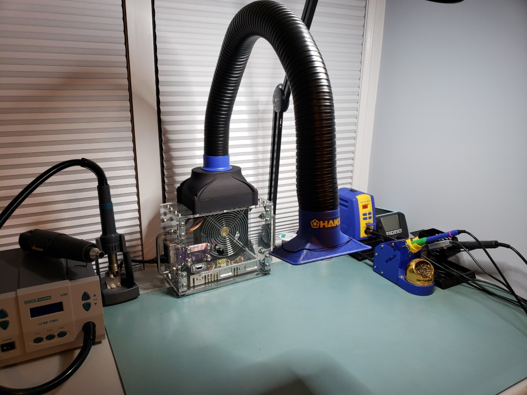
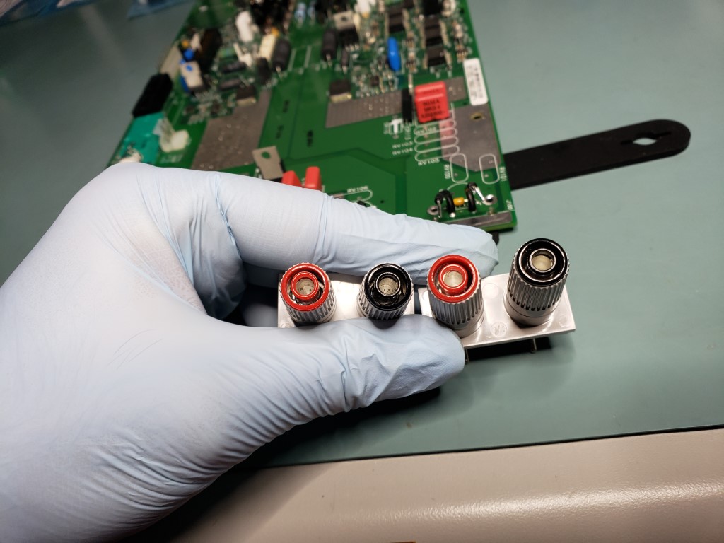
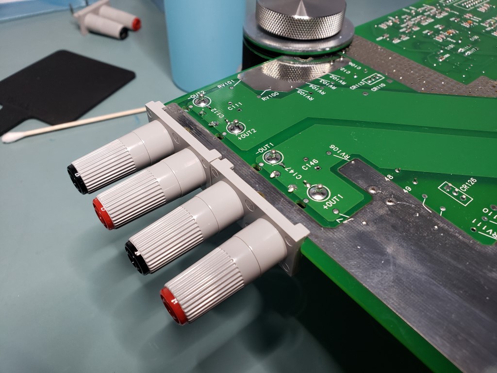
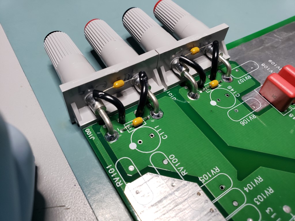
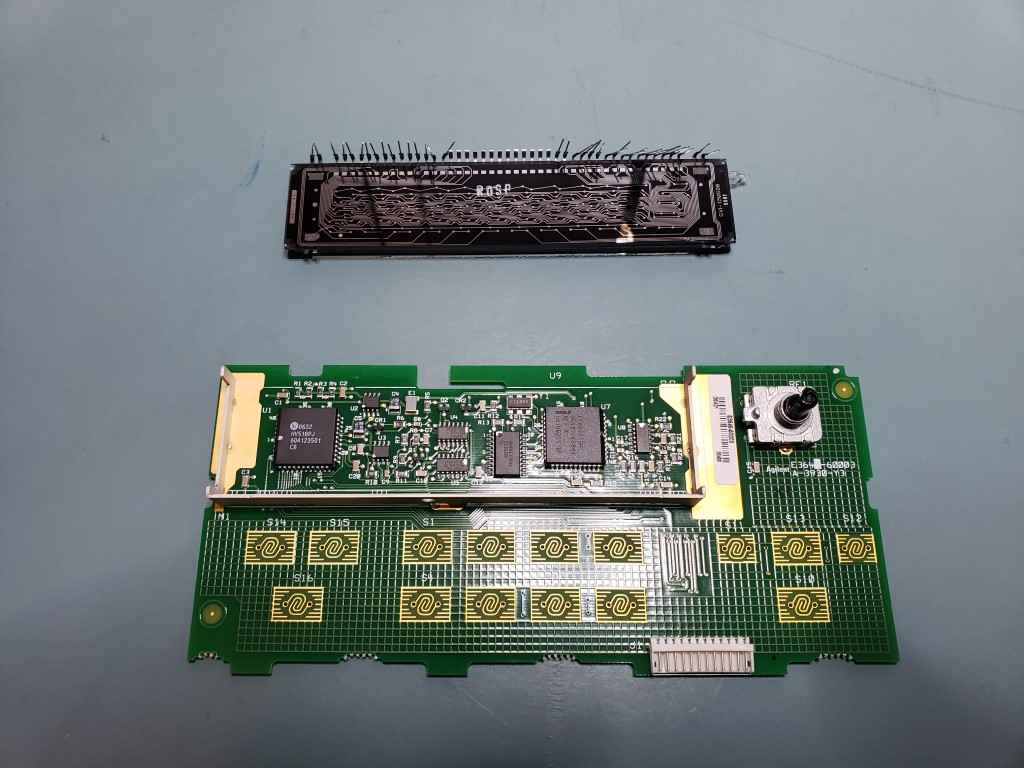
After putting the new box to the test with a few smoke-heavy soldering and desoldering operations (VFD, binding post, and capacitor replacement on an eBay score Agilent E3648A power supply), the room did not stink nearly as much as it would have without my new fume extractor.


If I had to guesstimate the bill to buy and replicate this fume extractor, the total would be between $500-700 USD in raw materials alone. The 3D printed filter box and plenum were the priciest parts, followed by the Hakko C1571 duct kit, the San Ace 9LG fan, laser cut acrylic panels, all fasteners, corner brackets and other metalwork, and the electrical components. Then factor in all the sweat equity for designing, physically assembling the prototype, and developing firmware. This is not a quick and low effort project; it is intended to a durable and high performance solution for effectively removing solder smoke while meeting all of the design goals as stated in the beginning of the article. That being said, the time and effort spent on this project should pay dividends for all the soldering I have planned across various future projects!

Very impressive project. What CAD software do you use?
LikeLike
Thank you! I use Solidworks 2016 for general CAD design and KiCAD for PCB designs.
LikeLike