
Specialized soldering tools can save lots of time and effort. In the case of both surface mount and through hole rework, a comfortable pair of hot tweezers is awesome for removing 2 terminal devices. Resistors , capacitors, and small ICs can be whipped right off the board without using hot air tools that can accidentally blow other components away or cause unintentional damage from delivering too much heat.
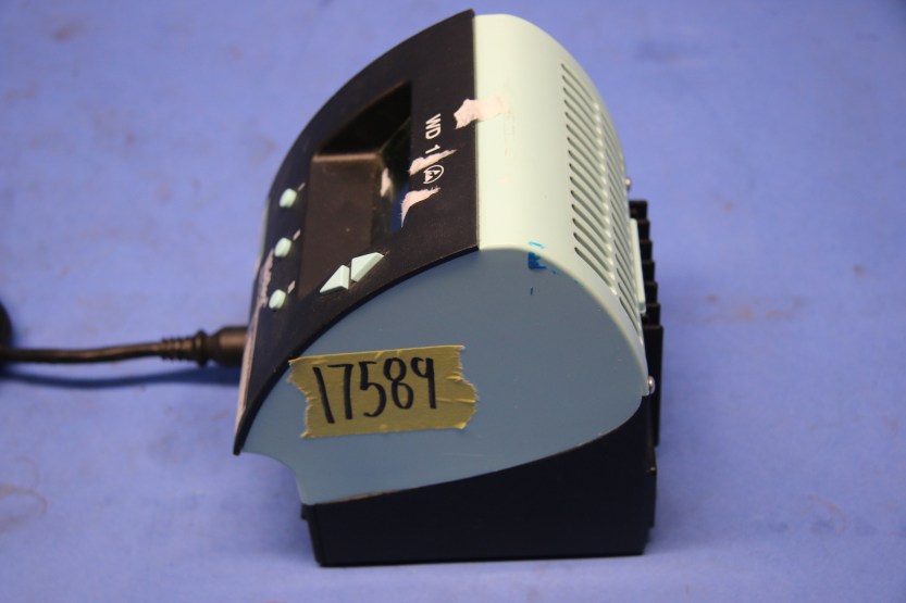
I picked up a set of weller WTA-50 tweezers on eBay when I first started down this path. I also bought a weller WT1 station to use with it. Any hot tweezers is better than none at all, but once I started working with 0603 and smaller components, the WTA-50 became difficult to use. Thankfully, weller makes a much smaller, more nimble, and high power set of tweezers in the later WMRT lineup. Unfortunately, the WMRT tweezers are not compatible with the WT1 base station (don’t get me started with how silly this is). The only reasonably priced base stations available for the WMRT are used WD1M units. I’m sure the WD1M is plenty reliable, but it is a real clunker; it doesn’t stack so it takes up lots of bench space, plus the user interface is awful. And it’s ugly.
Thankfully I happened across this web page which presented a project that met my needs very well: http://kair.us/projects/weller/index.html
In essence, this project is (in my opinion) an elegant and simple soldering iron controller designed to be neatly packaged in an off-the-shelf enclosure. After reading through the project page I was convinced that this would be the best choice for bringing my WMRT tweezers to life.
I started with ordering the boards. I ordered mine from PCB way as the project is conveniently shared on their site and prices are comparable to any of the competing board houses.


Digikey and Mouser bring happiness as always:
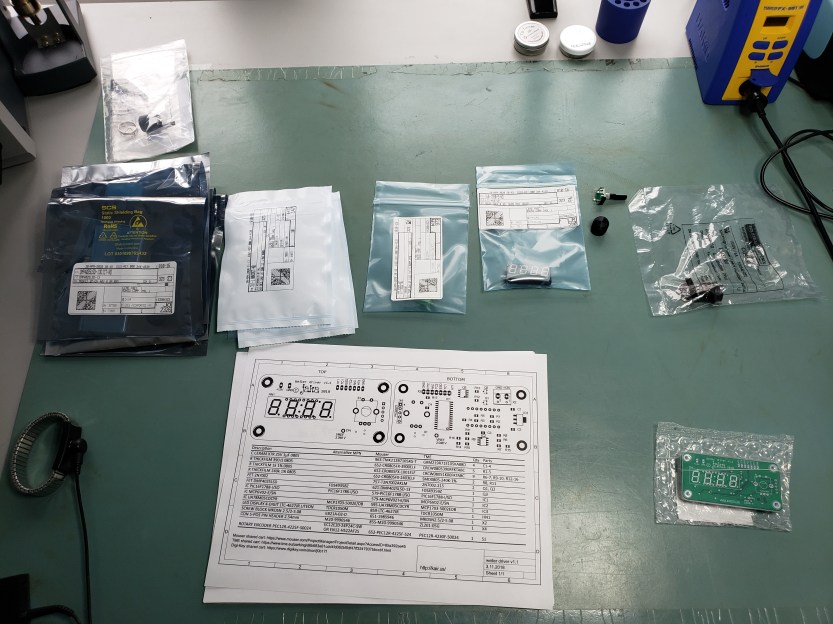
A short while later


Time to plan the chassis layout. I don’t have a milling machine, so I decided to get the chassis panels 3D printed with the appropriate “cutouts” for all of the plugs and user interface. I had them printed using HP multi-jet fusion PA12. The final parts were impressively strong and functional. Of course, it always helps to do a virtual fit check first:


The power supply I selected is a Traco TPP 150-112A-J. It is a medical grade 150 watt AC/DC power supply built to a very high standard. No knock-off components in this bad boy. Double I/O isolation, < 100μA earth leakage, PFC > 0.95, < 0.3 W no-load standby, 91% efficiency, and 150 watt output (12 VDC @ 12.5A) all in a 2.0″ x 4.0″ package. It isn’t cheap, but if this is a tool I plan on using for many years, why cheap out on such a fundamental part? Additionally, there is no airflow inside the case I am using. If I picked a cheaper and lower power unit, the chances of it running hot and being short lived are much higher.
After getting the 3D printed panels and a few painstaking hours of carefully measuring, cutting, soldering, and heat-shrinking all the wiring (18 AWG for power – 20 AWG for signal – all PTFE insulation), I brought the unit to life!


I have to say that the assembly work was quite tedious. The 0905 enclosure is just big enough to cram all of the parts in – it takes careful work to neatly wire everything up, and make sure no wires are pinched or connectors are strained. However, I am extremely happy with the end result. The feel, performance, and looks of this controller have exceeded my expectations! The user interface has a short learning curve, but is easily understood after a few minutes. The rotary encoder is de-bounced nicely in software so that inputs are smooth and tactile. The 80 watt WMRT tweezer heats up very fast at the default duty cycle settings and temperature is stable even under heavy thermal loads. Response time is equally impressive and temperature rarely oscillates or overshoots. I couldn’t be happier with the outcome and I look forward to using this controller to solder many future projects!

One thought on “DIY Weller WMRP/WMRT soldering station (open source)”