
After acquiring the E3200 extender (teardown link here) I was quick to learn that it is not useable without a compatible primary router managing the LAN. Since I’ve been rocking the good old G1100 (quantum) gateway for many years, it was time for an upgrade.

While I could go with an aftermarket router, sticking with a Verizon branded unit simplifies setup, especially for MoCA and other coax connected appliances (set-top boxes etc).
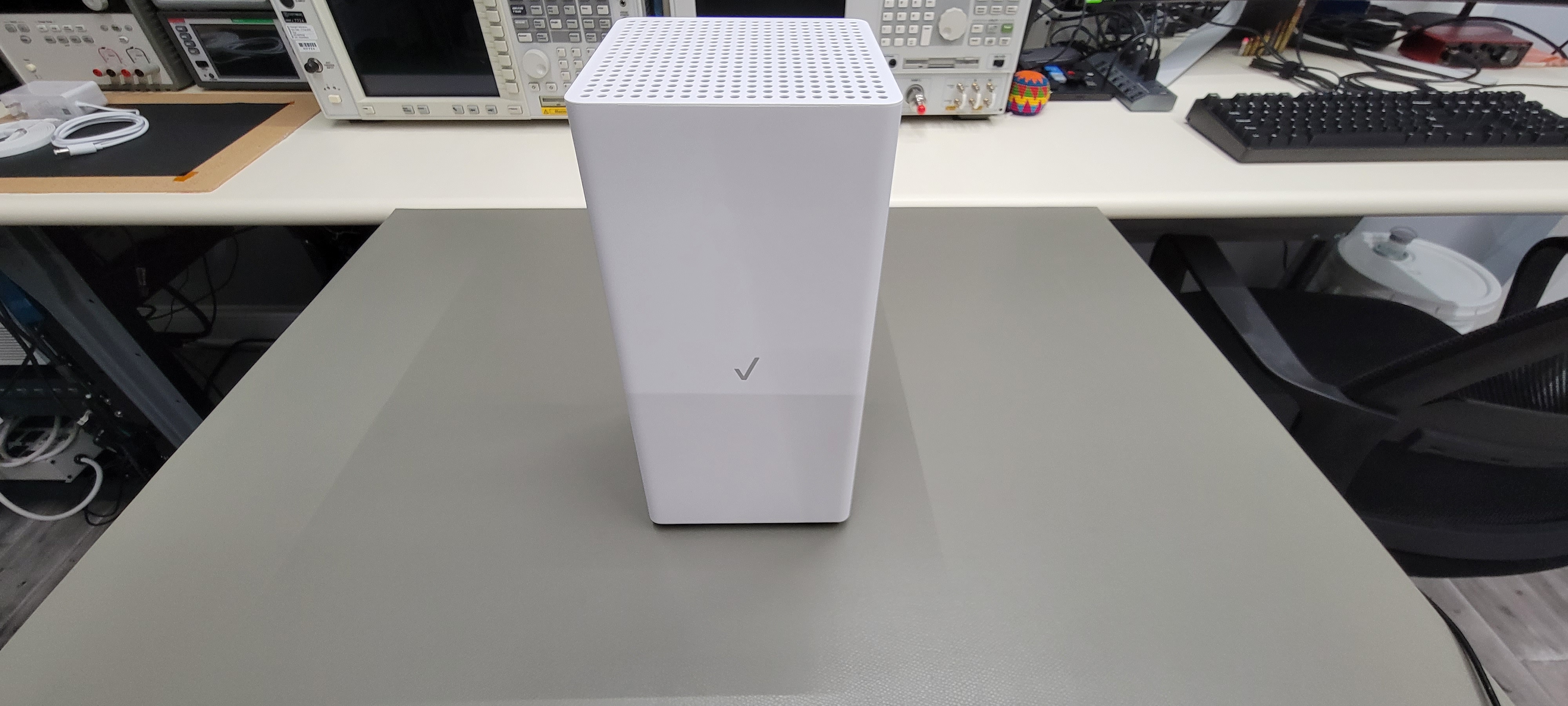
I found a deal on a new in-box CR1000A and decided to pull the trigger.

Basic specs on the CR1000A are as follows:
- Radio:
- One 2.4 GHz 11ax 4×4
- One 5 GHz 11ax 4×4
- One 6 GHz 11ax 4×4
- Up to 160 MHz channel BW
- Backhaul connectivity:
- One 10 Gb WAN port
- One 10 Gb LAN port
- Two Gigabit LAN ports
- One MoCA 2.5 Type F LAN coax port
- Embedded computer:
- 4 GB Flash
- 2 GB RAM
- CPU off-load for 11ax chipset
- Software:
- TR-143 SpeedTest
- Misc. security features (McAfee)
Getting inside this unit requires a bit more effort than the E3200 extender I looked at previously. First, the top cover pops off with some careful prying around the edge. This gives us access to 3 screws that attach to the antenna mast.
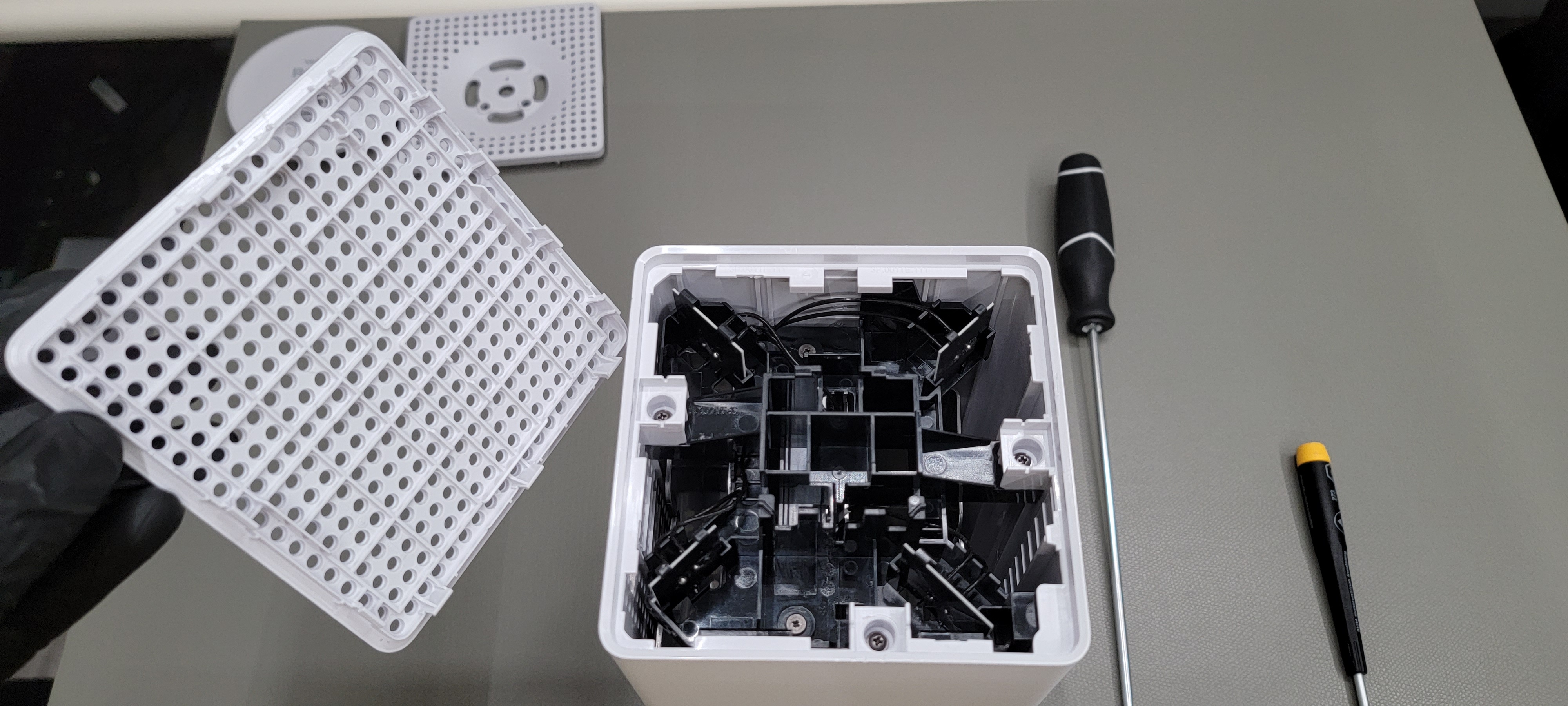
Next, remove the base by taking out 3 screws. 2 of them are hidden under the label.

After all 6 screws are removed, the internal assembly slides out of the bottom.
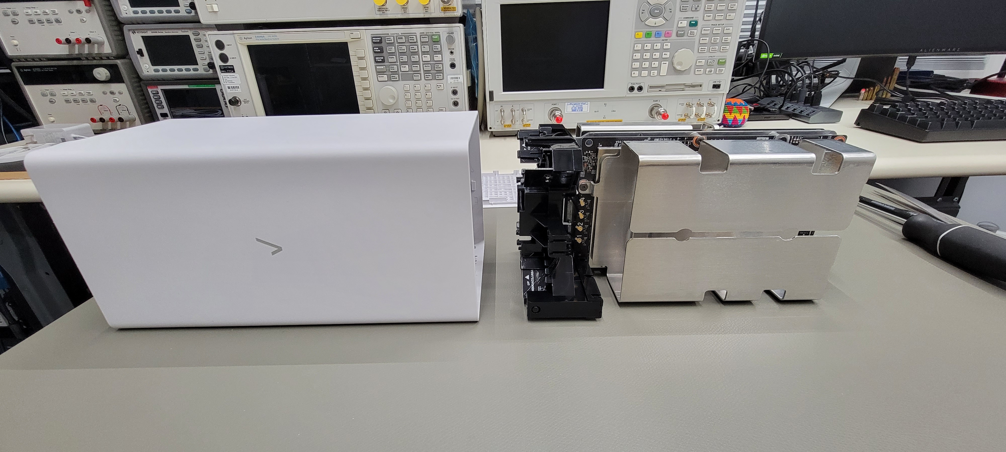
Construction is very similar to the E3200 at first glance. 2 PCBs sandwiched against the chassis, antenna mast at the top. Large passive aluminum heatsinks on both sides.
Looking closer, it appears that both boards have RF front ends. Based on this, the layout might not be as simple as a digital-only board and an RF-only board.
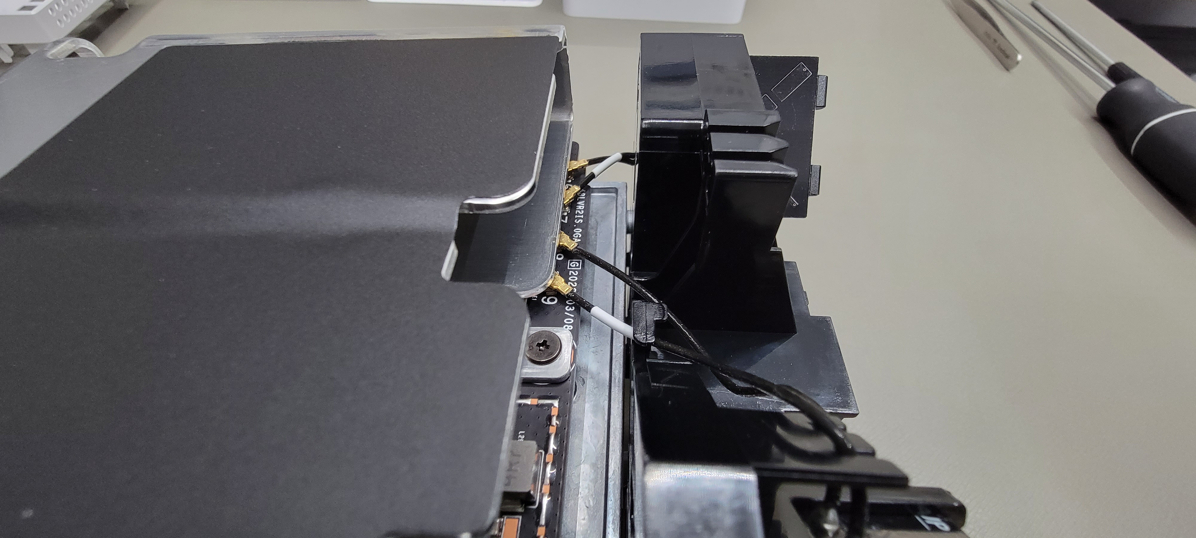
The heatsinks need to come off first, as they are covering the micro-coax connections for the antennas. More of the pink thermal putty that smears everywhere.
Separating the boards, we find that there is only one high density digital interconnect between them.
Starting with the board that has the ethernet/power input/USB-C connectors:
Ethernet PHY section first:

The outer 2 ICs are for the 10 Gb WAN and LAN ports, the inner two ports are 1 Gb LAN. Notice that 10 Gb PHYs have heatsinking putty while 1 Gb PHYs do not.
The 10 Gb ethernet ICs are Marvell AQrate AQR113C-B1-C Gen 4 ethernet PHYs. They support up to 10GBASE-T over “more than 100 meters of twisted pair cabling (assuming CAT.6A)”.

The 1 Gb ethernet ICs are Realtek RTL8221B ethernet PHYs which operate up to 1000Base-T over a limit of 140 meters of CAT.5 cable.
The switch section is run by one large BGA IC:
The switch IC is a Realtek RTL9303 which is described as a Layer3 switch with up to 8 ports of 10G ethernet. It contains an 800 MHz MIPS-34Kc CPU and supports a maximum of 64 MB SPI NOR flash, 1 GB DDR3 SDRAM. The part also contains 64KB of embedded SRAM. Maximum throughput is 160 Gbps. I don’t see any memory, only the SN4T774 transceiver IC nearby.

Moving over to the RF section on this board. The shielding can is marked (6GWIFI), so one can assume that this is the single 6 GHz 6E 4×4 front end.
The main RFIC on this board is the Qualcomm QCN9024, which is a WiFi 6E chipset that operates between 5.15-7.125 GHz, has AP and STA functions with 4×4 MIMO and 4 spatial streams:

The RF front ends are Skyworks SKY85784 WiFi 6E modules which integrate a PA, bypassable LNA, and T/R switch along with passive coupler. TX gain is 33 dB, RX gain is 16 dB. Maximum output power is +19 dBm. Note that these are 6E modules for the 6 GHz band, with a rated operating frequency between 5.92 GHz to 7.12 GHz. There is an option to enable or disable 6 GHz radio; when disabled it is likely repurposed for 5 GHz operation.
Looking near the USB-C connector, there appears to be one can that is soldered down. Of course, we have no choice but to de-solder it and look underneath.
Unfortunately, there was nothing interesting:
On the USB-C connector side, there is one IC in the immediate vicinity of the connector
This part is a PI5USB30213A which is a bi-directional mux/switch for USB 3.2 Gen 1 connectors. This likely handles the reversible plug nature of Type C.
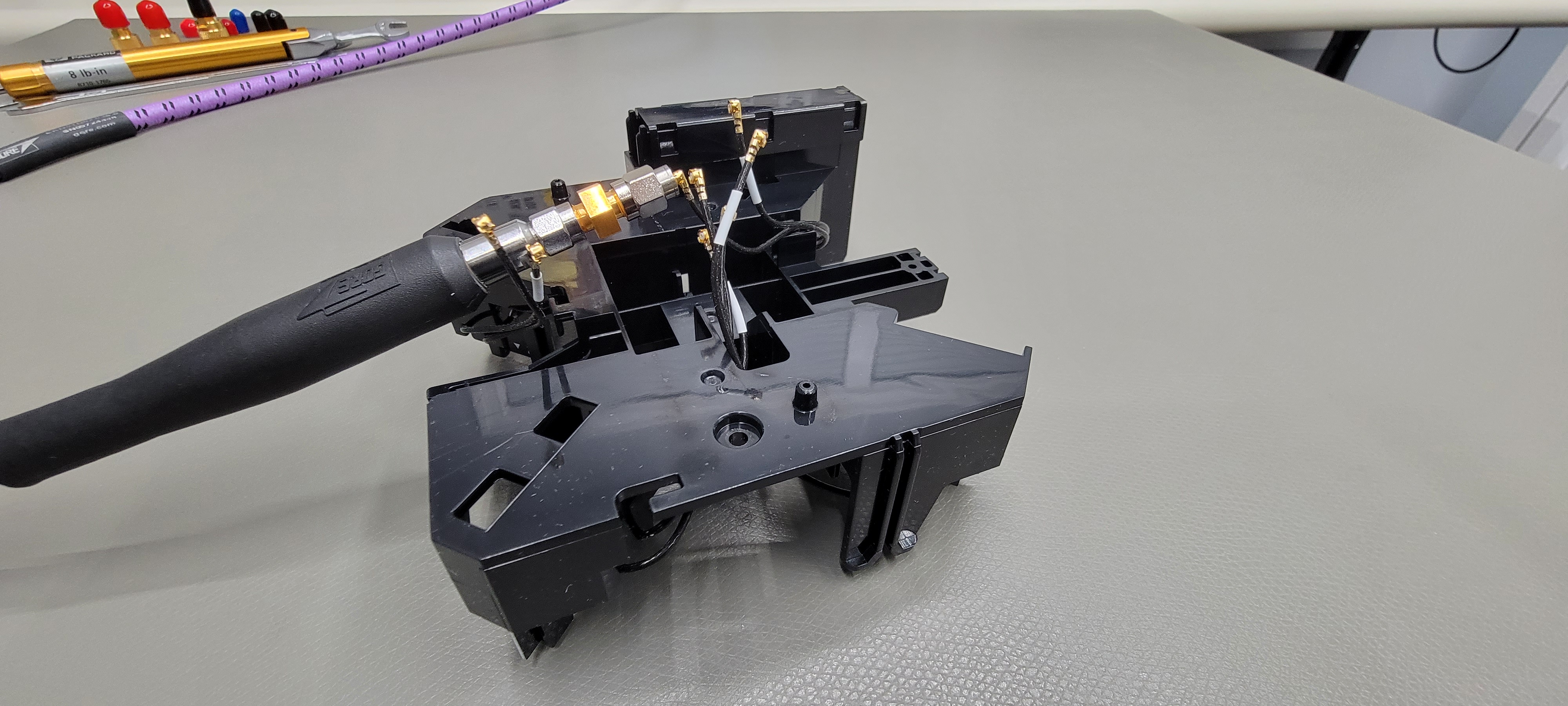
That’s about it for the one board. Now onto the second board which appears to contain the main CPU, MoCA chipset, and an additional RF front end.
Starting with the RF front end, we have 8 channels which are shared between 4 antenna ports.

The 2.4 GHz RFIC on the left (pic above) is the Qualcomm QCN5024. 2.4GHz RF/PHY/Radio, 4x WSI, Wi-Fi 6, MU-MIMO, 1024QAM.

The 5 GHz RFIC on the right is another Qualcomm QCN part in the 105DRQFN package, likely the QCN5154. The package markings are extremely light on these parts; I can barely read them even in well lit high resolution shots.
For the front ends, we have (4) Skyworks SKY85333-11 modules for 2.4 GHz and (4) SKY85747-11 modules for 5 GHz. These feature similar integrated PA and bypassable LNA with integrated coupler, ~34ish dB of TX gain and ~16ish dB of RX gain, with a max output power around +19 dBm.
The CPU is a Qualcomm IPQ8074 SoC. It contains (4) Arm Cortex A53 processors up to 2 GHz clock. For driving WiFi 6, it supports a maximum throughput of 4.8 Gb/s across 2.4 GHz and 5 GHz bands, with potential for 4×4 MIMO for 2.4 GHz and 8×8 for 5 GHz. It supports external DDR3L or DDR4 RAM, external NOR or NAND flash, and contains many popular peripheral interfaces on-chip such as ethernet, Bluetooth, USB 3.0, PCIe, and more.
It has (2) Samsung K4A8G165WC-BCTD DDR4 RAM chips, 8 Gb each, 2666 MHz
I kind of skipped over the flash BGA, its just some embedded flash…
The MoCA section at the bottom. Not much on this side of the board:
Flipping over we find the MaxLinear MXL3711, which is a MoCA 2.5 (2.5 Gbps) chipset. It operates an RF between 400 MHz to 1675 MHz.
That sums up the two main PCBs.
Moving onto the antennas: we have 8 in total across 4 individual PCBs. 4 are dedicated to the 6E (6 GHz) front end; these are numbered 6, 7, 8, 9. The other 4 are on the shared 2.4 GHz and 5 GHz board, numbered 1, 2, 3, 4.
Antenna number 5 is not used as the corresponding coax connector is unpopulated, next to more empty footprints for some kind of SoC module. Perhaps for some kind of Bluetooth feature that was not implemented?

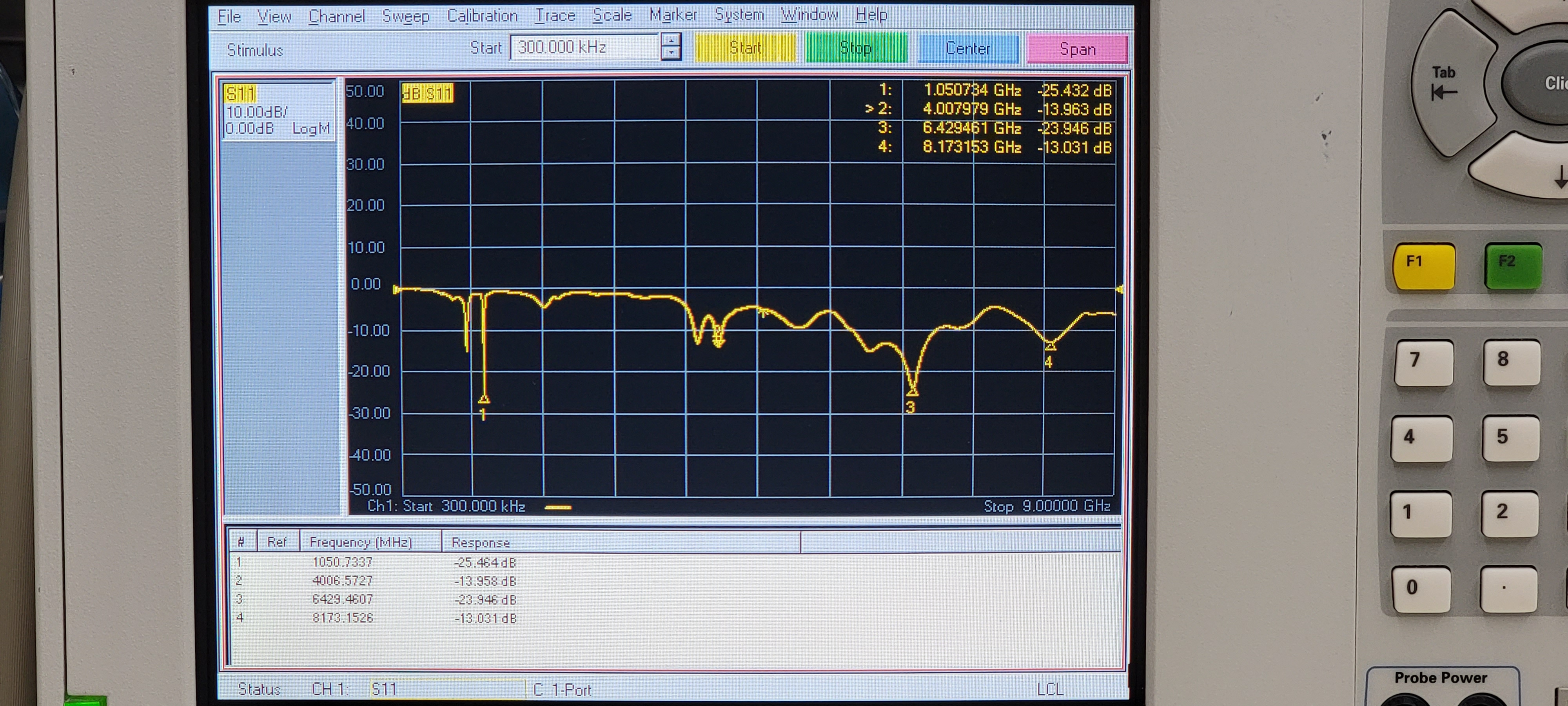
Making some return loss measurements. Setup is same as before with the E3200:
- Agilent E8358A PNA vector network analyzer (300 KHz – 9 GHz)
- 6401 point sweep
- 5 KHz IF BW
- 0 dBm test port power
- Anoison PA5125A 3.5mm M to Type N M adapter
- Gore Phaseflex EKD01D02036.0 test port cable (3.5mm F-M, phase stable, 36″)
- Agilent 5061-5311 3.5mm F-F adapter
- Agilent 85052B calibration kit (male open, short, broadband load)
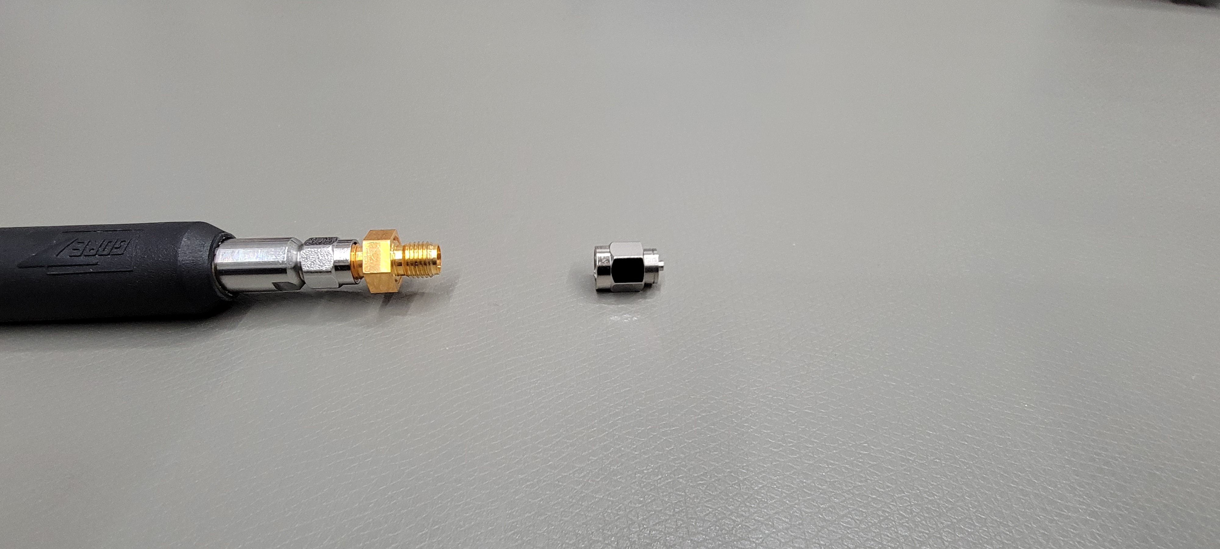
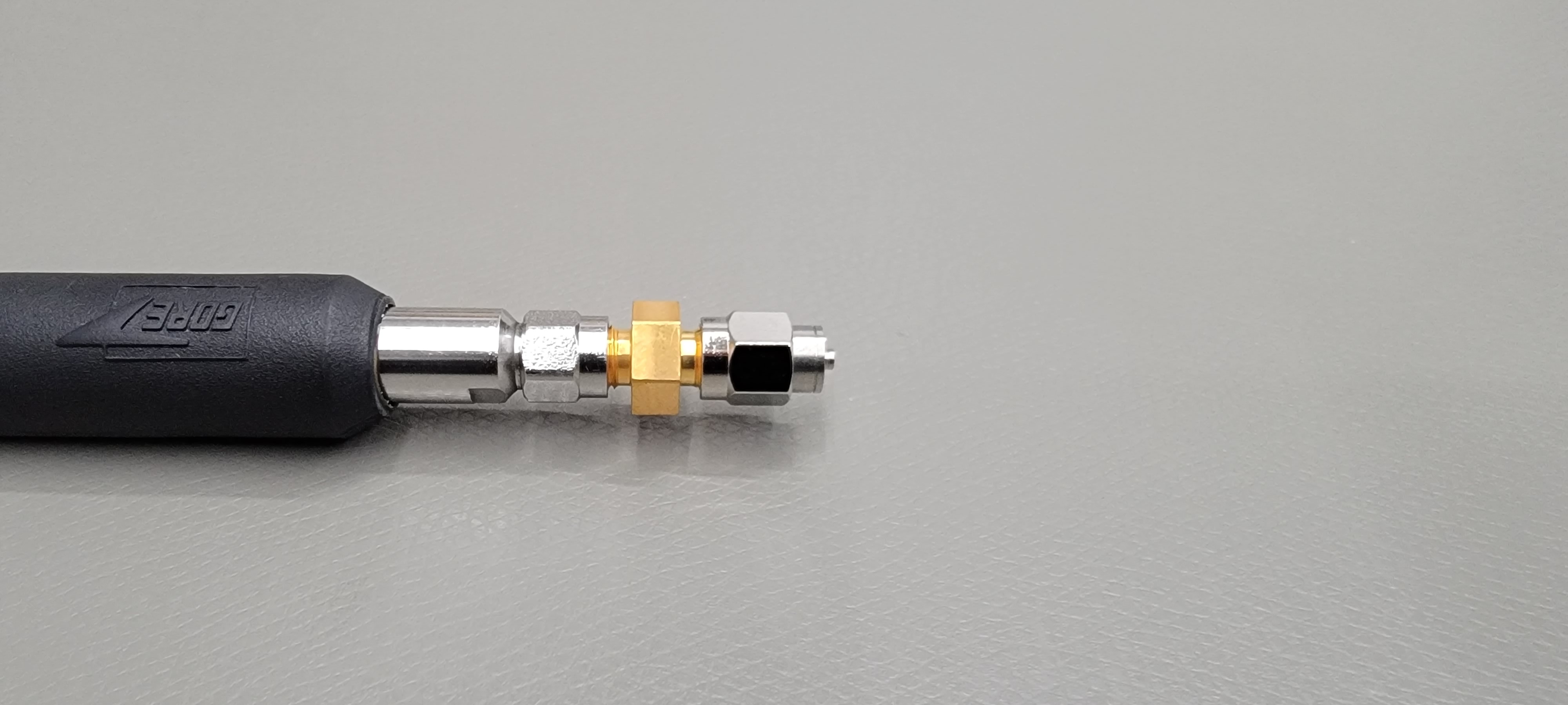
- Molex 0733860850 SMA to U.FL M-M adapter
1 port calibration up to 3.5mm F connector is flat under open. SMA-U.FL adapter doesn’t have too much of an effect on cal.
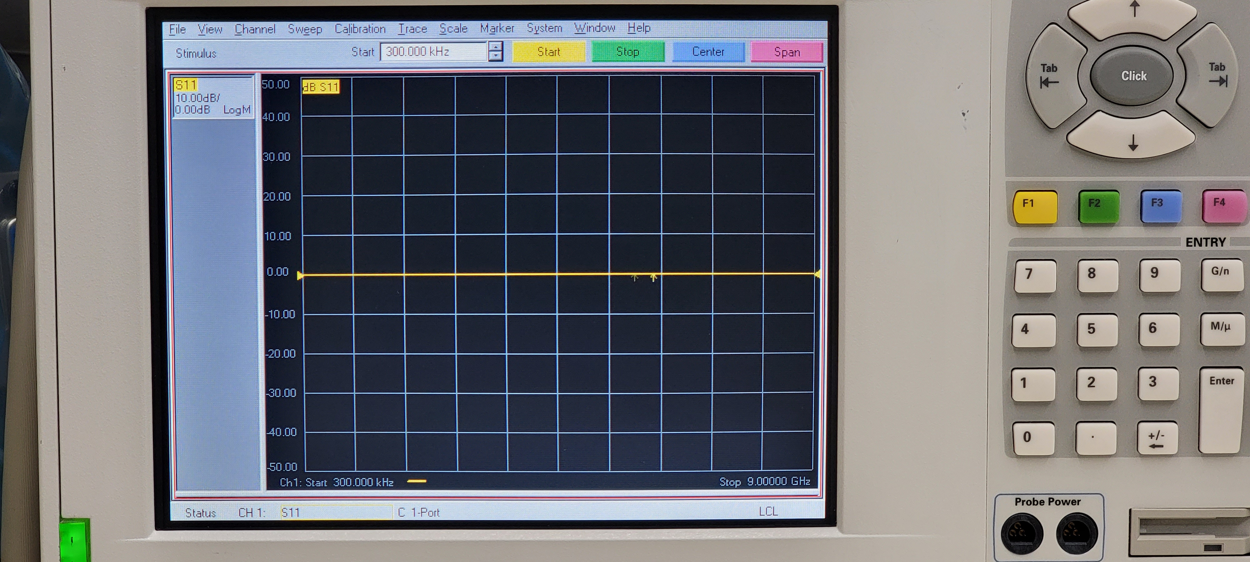
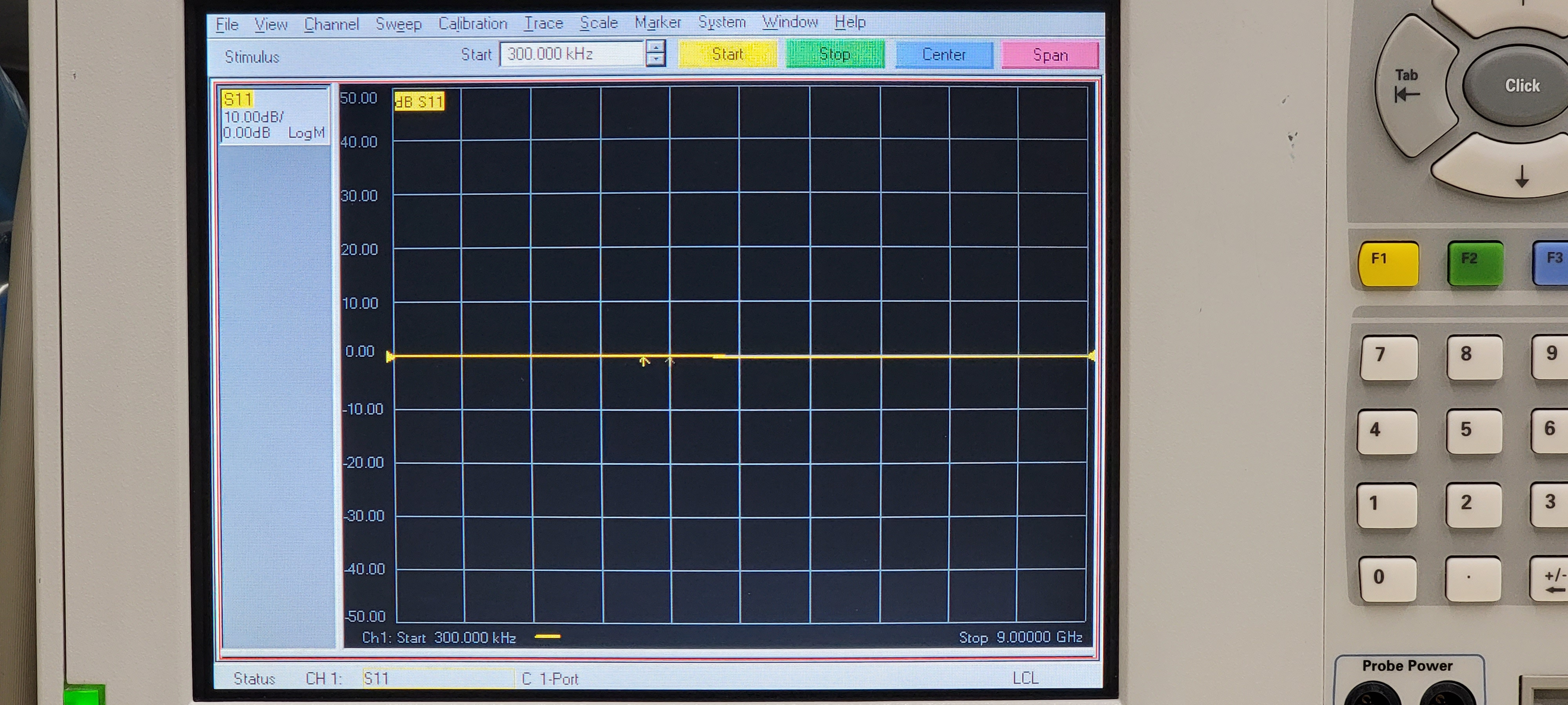
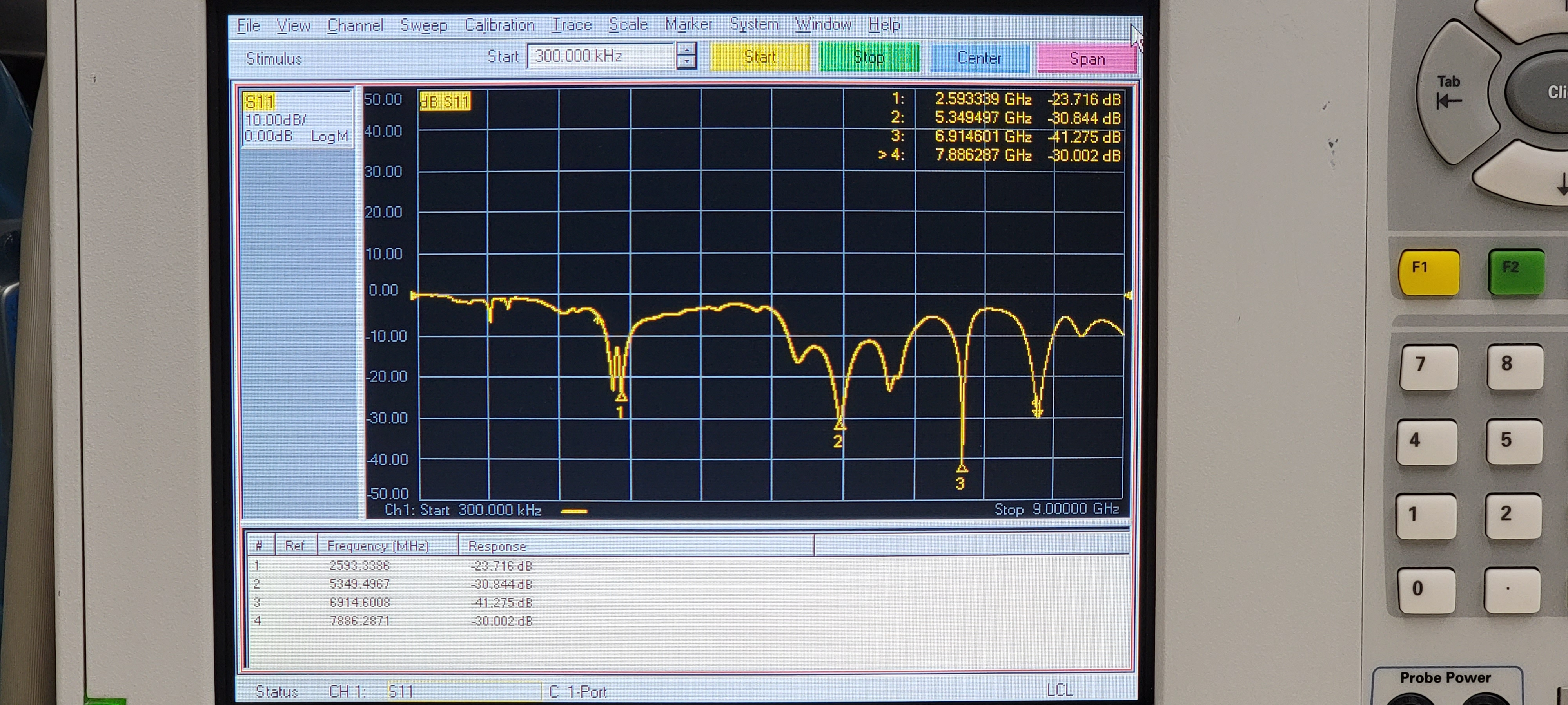
Starting with antenna #1 and moving in numerical order:
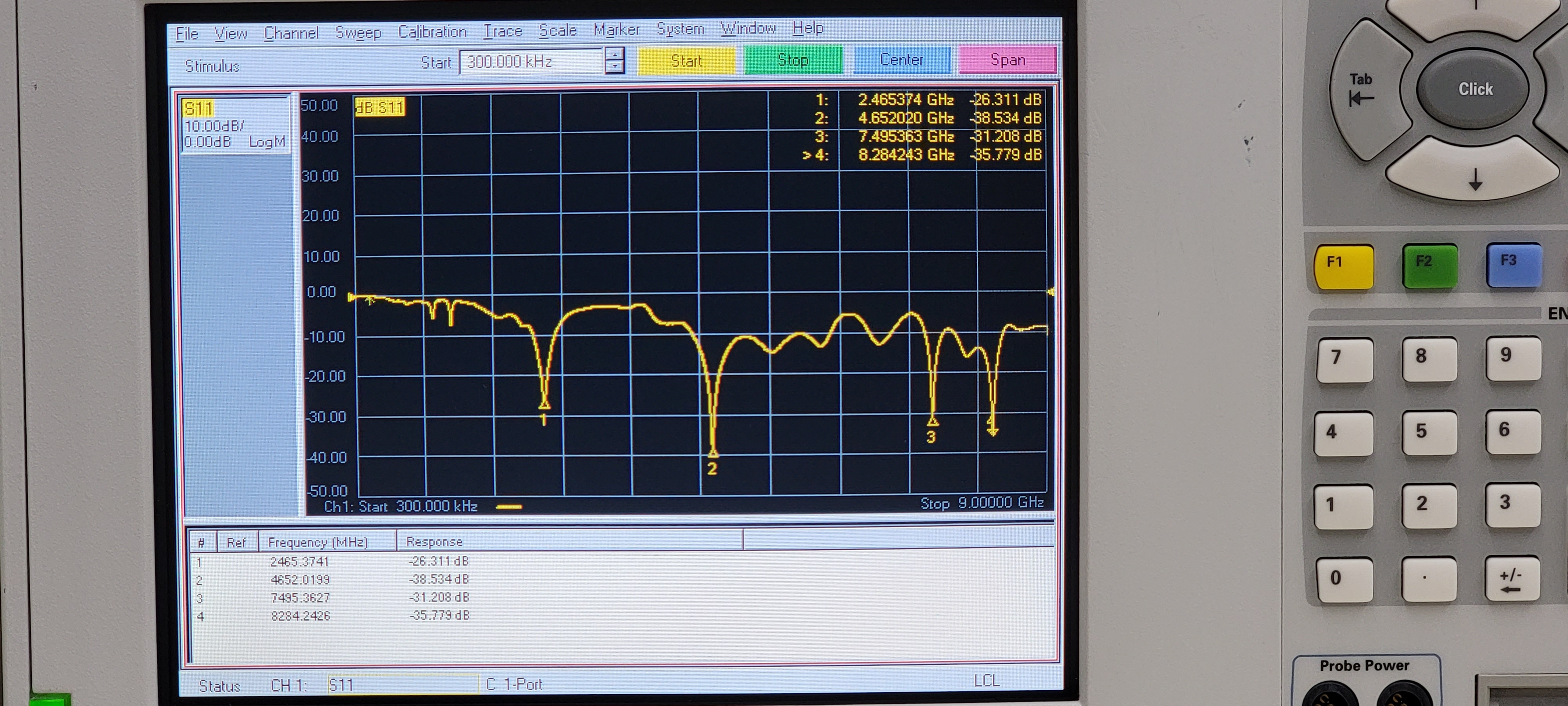
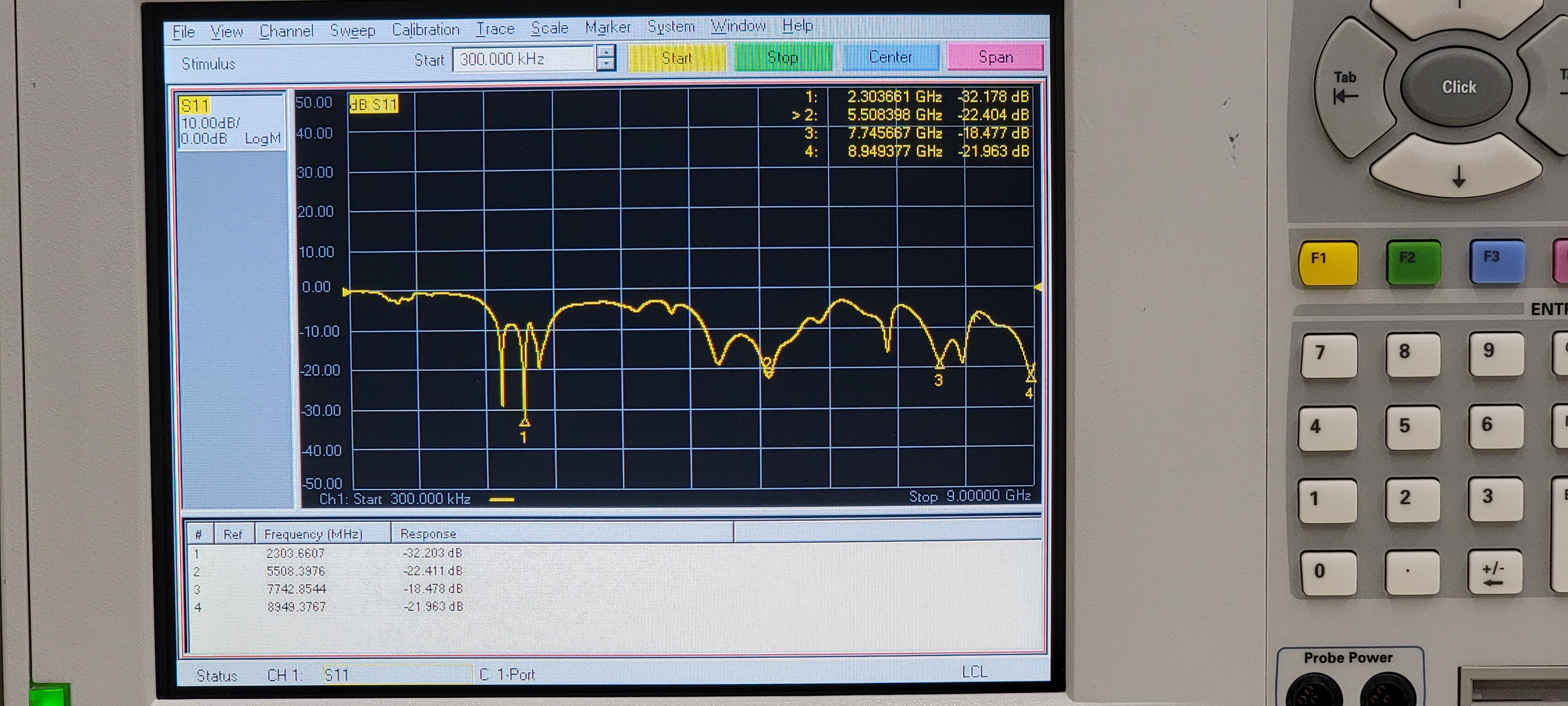
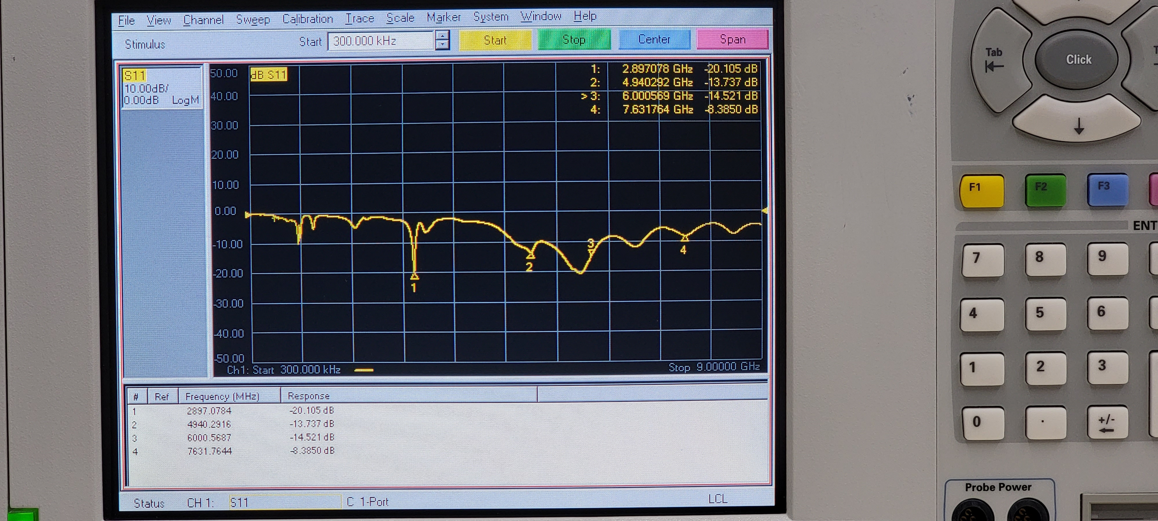
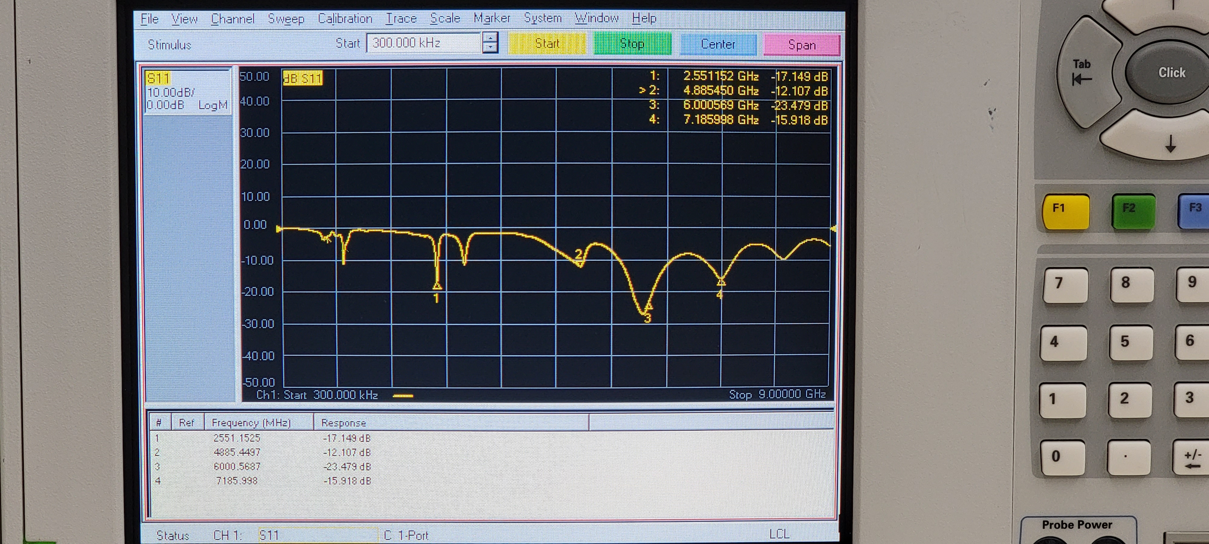
When I got to antenna #6, I noticed that the return loss was pretty lousy across the board:
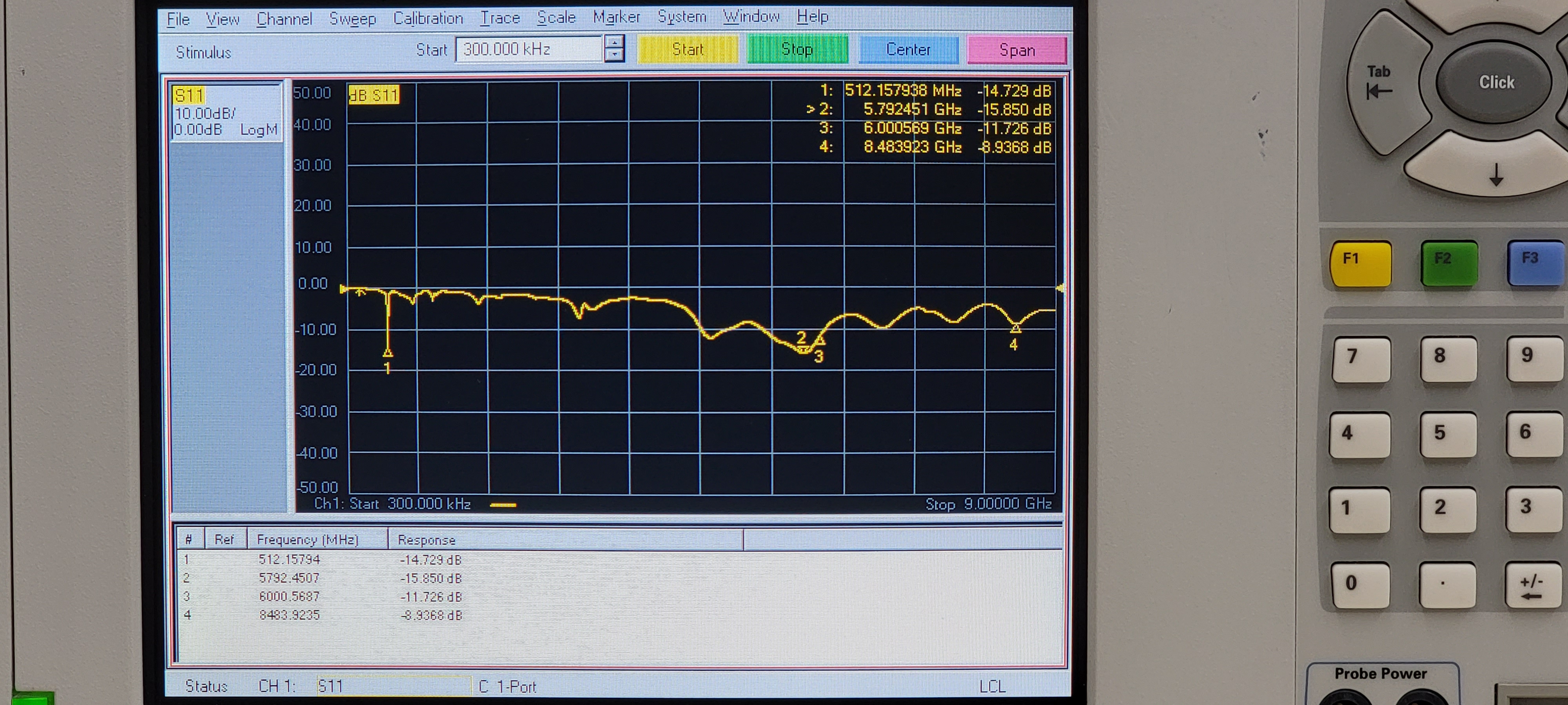
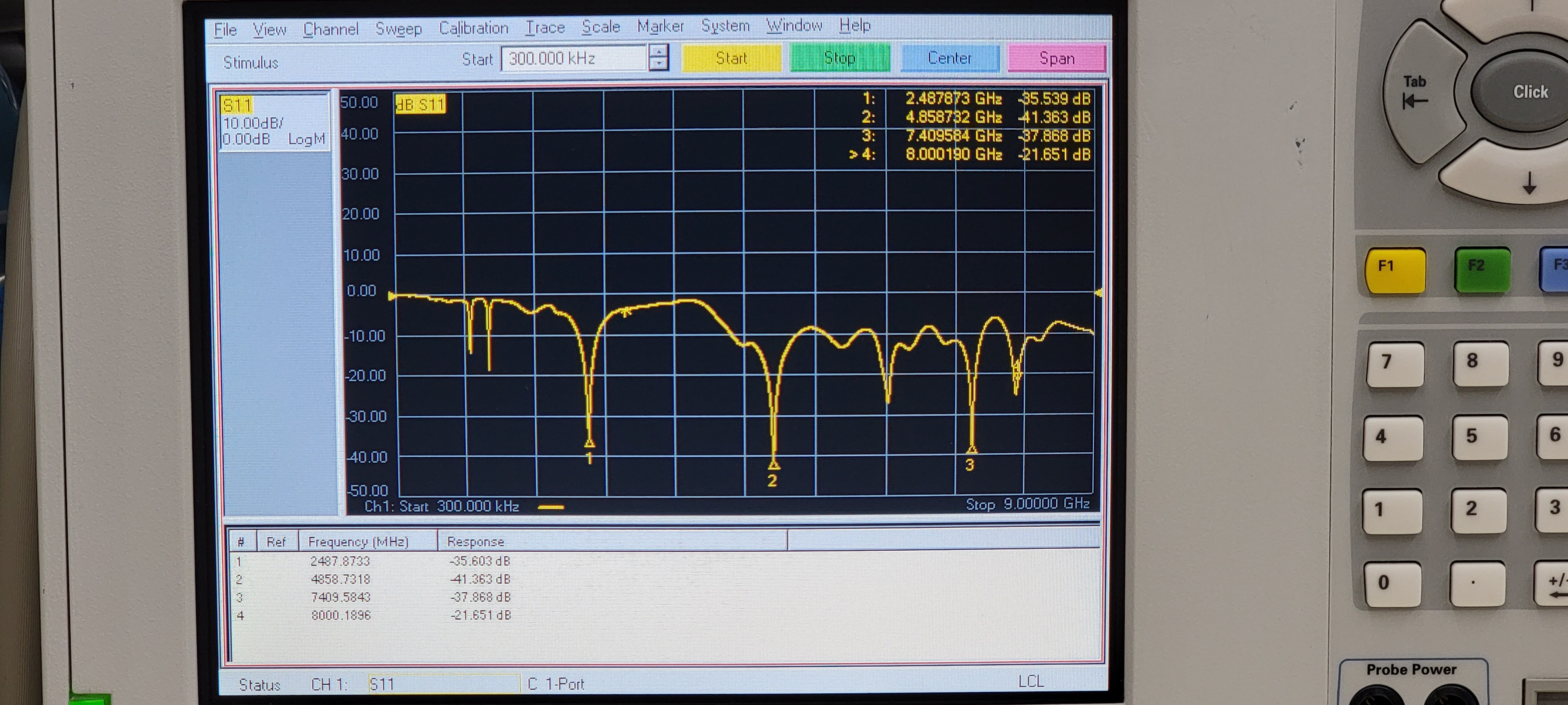
I tried touching up the solder joints between the coax cable and the PCB.
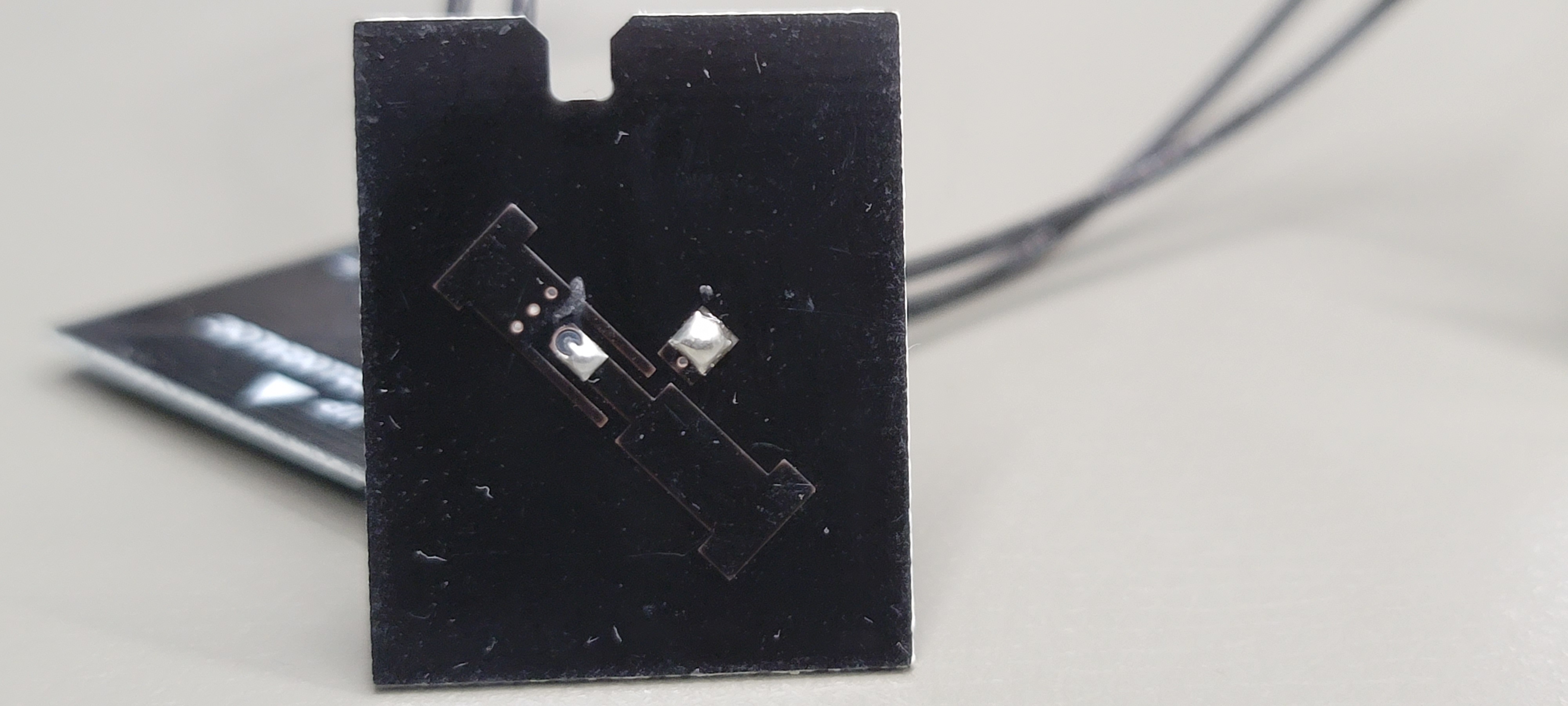
Return loss became a bit better. These are clearly hand soldered, and I’m not sure that each antenna is tested before being assembled into the unit..
Remaining antennas:
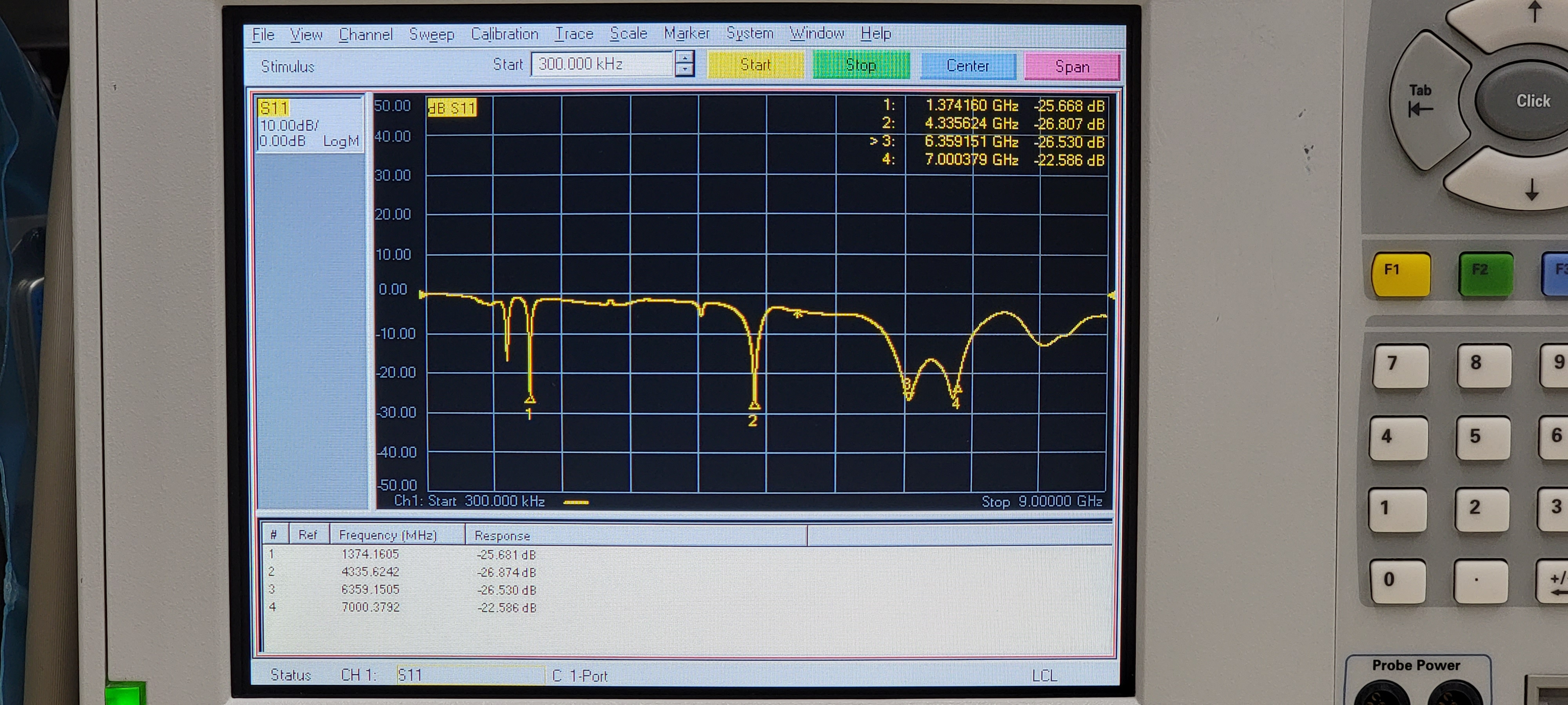
Recall that antennas 1, 2, 3, 4 are shared on the 2.4 and 5 GHz dual band channels, while 6, 7, 8, 9 are committed to the 6E front end. 6 GHz operation is optional, so if the user does not enable this then I’m sure the 6E radio is repurposed for 5 GHz operation, which is within the frequency range of the QCN9024 RFIC.
I’m not sure how much useful gain the SKY85784 front end has below 5.92 GHz which is the low frequency rating I found online; I’m sure it is still somewhat functional at lower frequencies since the guard band between upper 5 GHz channels (U-NII-4) and 6 GHz starting channels (U-NII-5) is theoretically only 25 MHz!
Thankfully everything still worked upon reassembly. My CR1000A and E3200 pair are now working well to provide good WiFi coverage and low latency over the air!
Stay tuned for more.

I understand that Verizon uses that coax port to install a network extender. I was not given a network extender with my Fios installation.
if I utilize an F-type coax to SMA adapter and attach an SMA WiFi antenna, will it improve my signal strength? if so, what specs on an SMA antenna should I look for?
LikeLike
The Type-F coax port on the CR1000A is strictly for MoCA purposes. Think of it as a wired ethernet port that uses coax instead of RJ45.
Attaching an antenna to this port will not do anything.
If you wanted to connect an extender, you would have to purchase one such as a Verizon E3200 and connect it via coax. This will act as a new wireless router and give you the signal strength increase you are looking for.
LikeLike