
Let’s take a look under the hood at a fairly popular consumer WiFi 6 device.


The E3200 is a WiFi 6 access point/extender made by Arcadyan Technology Corp. of Taiwan (Arcadyan model number: WG9116B), branded and sold by Verizon. Quick specs from the datasheet describe the following features:
- Radio:
- One 2.4 GHz 11ax 4×4
- Two 5 GHz 11ax 4×4
- Up to 160 MHz channel BW
- Backhaul connectivity:
- Two Gigabit LAN ports
- One MoCA 2.5 Type F coax port
- Embedded computer:
- 1 GB NAND
- 512 MB RAM
- CPU off-load for 11ax chipset
- Software:
- TR-069/TR-181
- Embedded webserver
Seems pretty standard for a WiFi 6 access point. Don’t turn it on, take it apart!
Undo 4 screws on the bottom and the main cover pops off.
The construction becomes immediately obvious. We have the black antenna mast at the top, and two PCBs with board-to-board interconnects sandwiched around a structural plastic chassis.
As we would expect, one PCB is dedicated the CPU/processor and backhaul, while the other handles the RF side of things.

Now, we can take a closer look at the PCBAs to see what silicon is being used.
First we will examine the CPU board. Note all the unpopulated footprints. I wonder what other products this board layout is used for?
According to https://wikidevi.wi-cat.ru/, this processor is also used in the Verizon G3100 router. Perhaps the G3100 and E3200 share the same CPU board, explaining the unpopulated parts?

Switching over to the RF board:

There are a total of 8 x 5 GHz front end modules and 4 x 2.4 GHz front end modules, hence the datasheet description of one 2.4 GHz 4×4 and two 5 GHz 4×4. One of the BCM43684s appears to have all 4 channels dedicated to 5 GHz, while the other two have 2 channels for 2.4 GHz, 2 channels for 5 GHz which are combined into a single, likely dual-band antenna.
Also, based on further missing footprints, I’m presuming that the G3100 router uses same RF board as well. Why not consolidate the router and extender layouts to the same 2 boards and simply populate as needed?
For funsies, I decided to do some return loss measurements on the 7 antennas in the mast assembly. Based on the hardware, we expect to see 3 antennas that are dual 2.4/5 GHz and 4 antennas that are for 5+ GHz operation.
Measurement setup:
- Agilent E8358A PNA vector network analyzer (300 KHz – 9 GHz)
- 6401 point sweep
- 5 KHz IF BW
- 0 dBm test port power
- Anoison PA5125A 3.5mm M to Type N M adapter
- Gore Phaseflex EKD01D02036.0 test port cable (3.5mm F-M, phase stable, 36″)
- Agilent 5061-5311 3.5mm F-F adapter
- Agilent 85052B calibration kit (male open, short, broadband load)
- Molex 0733860850 SMA to U.FL M-M adapter
As a side note, I understand that the VNA calibration is not “perfect” as my calibration plane is only up to the 3.5mm F adapter, so the SMA to U.FL adapter was not de-embedded (or corrected?) in the measurements. Dutch company MegiQ does make a U.FL calibration kit, but a typical network analyzer calibration kit should include coefficients which further de-embed the nonidealities associated with real world performance of the standards (open, short, load, and though for 2+ port measurements).
As a sanity check, my “open” with the SMA to U.FL adapter attached (after SOL 1-port cal) was pretty flat, so it’s definitely good enough to make some rough measurements. Also, I’m not exactly doing this in an anechoic chamber. Strong enough background RF coupling into the antennas could certainly raise the noise floor of any measurements.

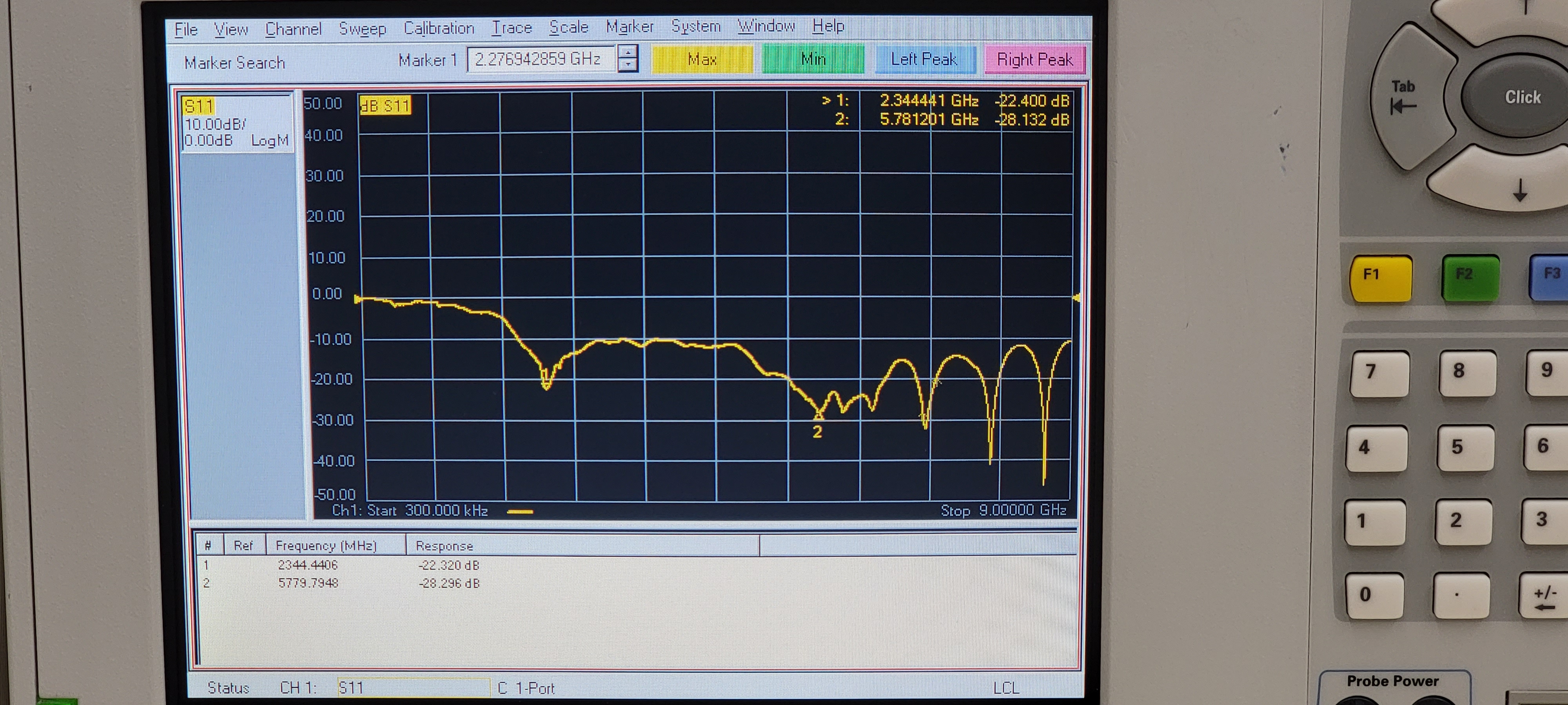
Starting with the three antennas connected to the dual 2.4/5 GHz channels (white, black, grey cables on connectors numbered 1, 2, 3 respectively):

And now the four antennas on the 5 GHz only channels (red, green, blue, yellow, on connectors numbered 5, 6, 4, 7 respectively):
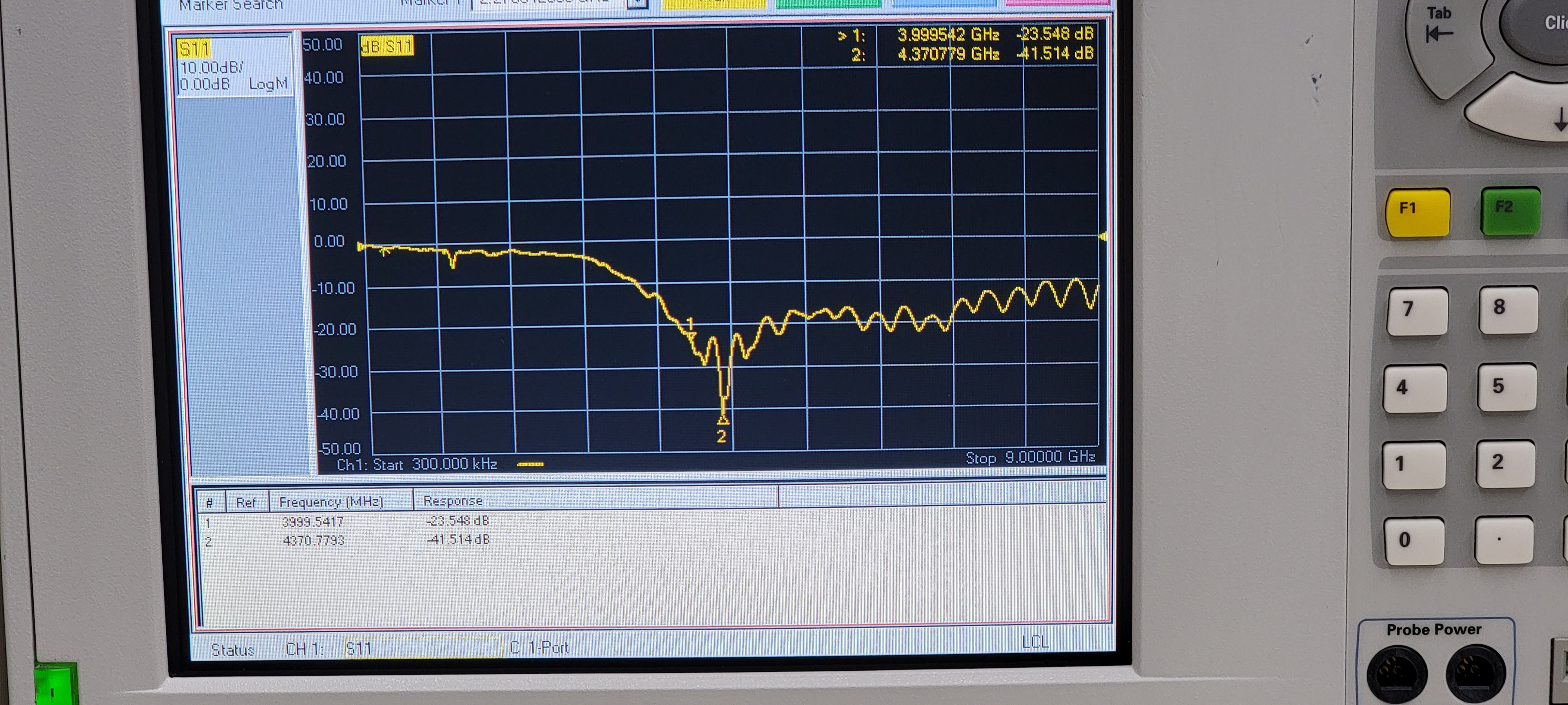
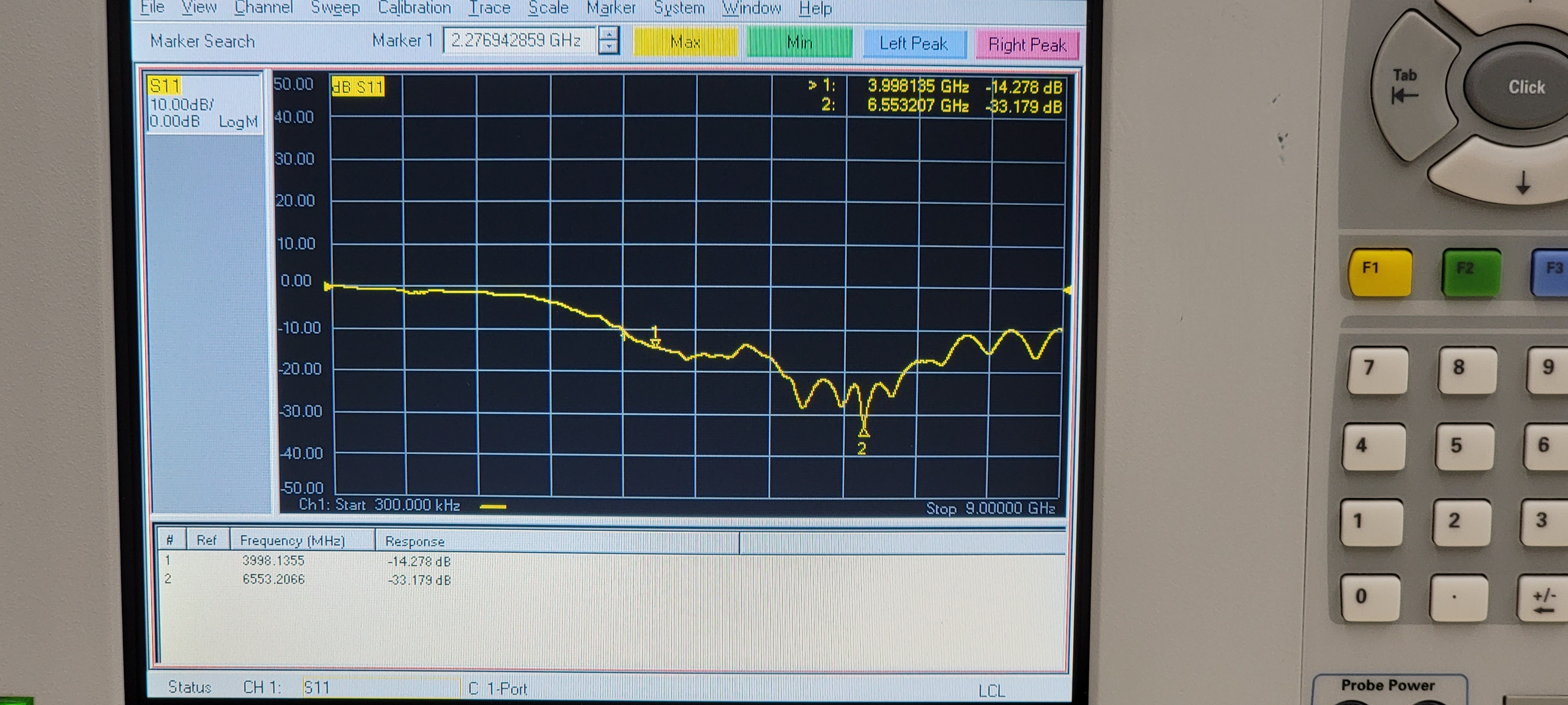
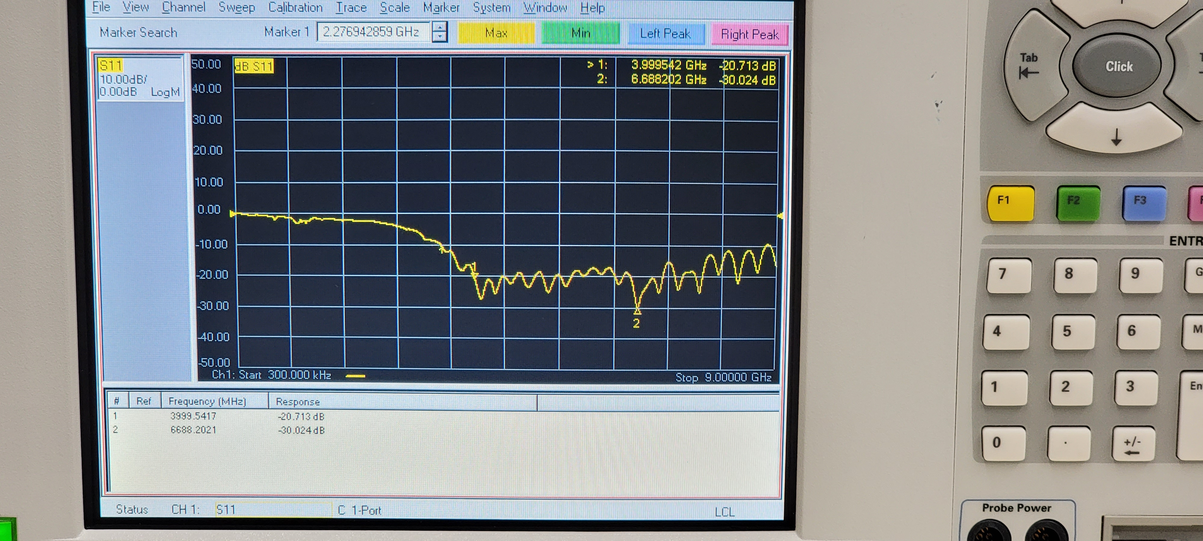
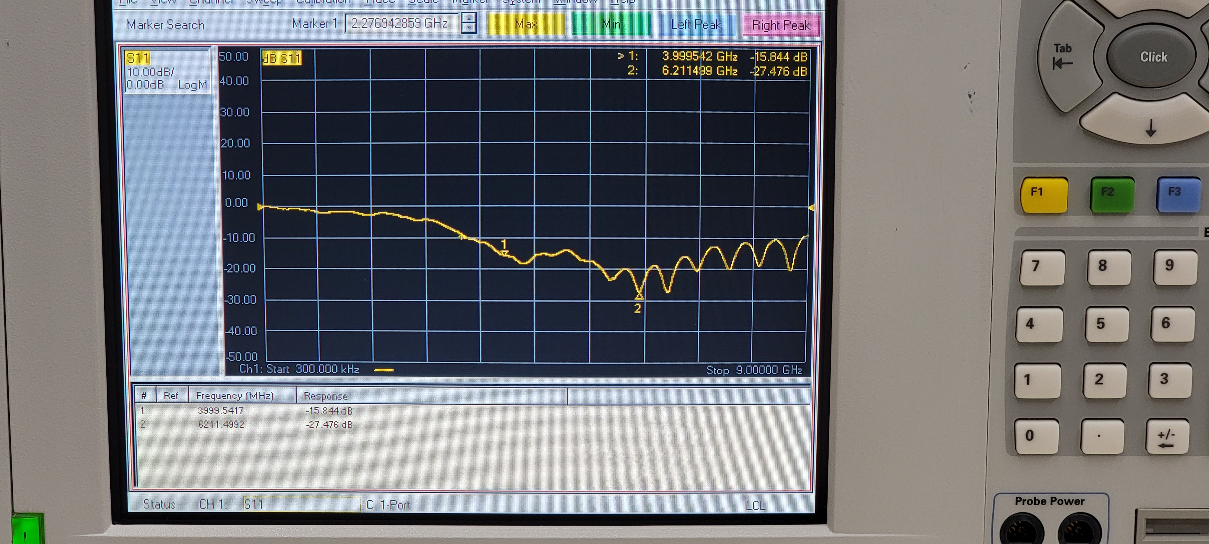
Antenna performance is pretty decent and within the expected bands. Minimum in-band return loss is 15-20 dB with the typical being a bit better in some cases.
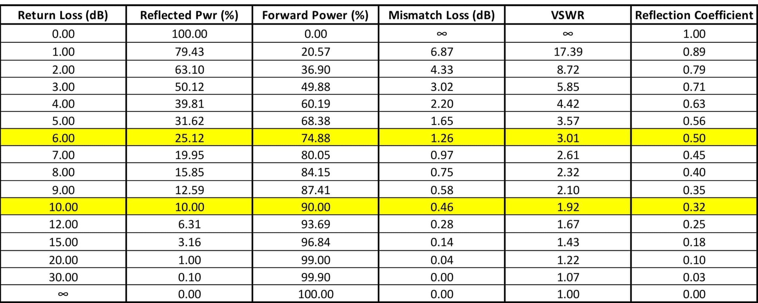
For reference, here is a table which represents the return loss vs percent reflected/forward power. A return loss of 15 dB means that nearly 97% of the power sent to the antenna is being forwarded, and the remaining 3% is reflected back due to impedance mismatches and other nonidealities in the system (connectors, cables, antenna itself).
That sums up this teardown of the E3200! I put it back together and the unit still works.
I’ve discovered, however, that one needs the correct Verizon branded router in order for this extender to function properly! Meaning that it cannot operate as a stand-alone extender without a combatable router (Verizon G3100 or CR1000A/B).
I tried a variety of things; connecting to a PC via ethernet and trying to access the webserver; connecting to my network, finding the IP address, and trying to log in; connecting to my Verizon ONT over MoCA. The unit just does not want to function on it’s own. The WiFi keeps turning on and off and the unit refuses to maintain a connection; the webserver is also unreachable (connection refuses).
I think Verizon has something going on with the firmware of this device to only allow communication through one of their selected wireless routers. Pretty annoying but it’s their box after all…
Maybe it’s time for me to upgrade anyway? I went ahead and snagged a deal on a new open-box CR1000A. I think you know what that means…
Stay tuned!

One thought on “Product teardown: Verizon E3200 (Arcadyan WG9116B) WiFi 6 Extender”