
Most practical circuits require passive components. The most common types of passive components are inductors, capacitors, and resistors. You do not need to be an electrical engineer to comprehend this fact.
Not all inductors, capacitors, and resistors are the same (which is also fairly obvious).
When you design a circuit, you need to know some basic information about the component you are selecting. Some of those important characteristics are the electrical ratings that are pertinent to in-circuit operation. Most components have an associated document called a “datasheet” which is supposed to spell all of this our clearly.
As it turns out, datasheets are sometimes akin to an advertisement which can play fast and loose with the actual part specs. Some OEMs have more creative marketing departments than others, but the responsibility still lies with the designer to select appropriate and reliable components for use in a marketable product. While most modern datasheets are comprehensive and formatted somewhat similarly, there is always the possibility of a spec not being present or clear which has important implications for your intended use.
So, how do we measure our resistive, capacitive, and magnetic components ourselves as designers? Seeing is believing, and one good test is worth a thousand expert opinions.
The answer is to use a proper LCR meter, LCR being an acronym representing inductace (L), capacitence (C), and resistance (R). An LCR meter is an instrument which directly measures the impedance of a component, and then uses math to calculate other useful values. The “impedance” of a component is defined by its resistance to the flow of a AC (alternating current) at a given frequency.


Most LCR meters are of the handheld variety. Similar to multimeters, they are useful for quick and general purpose electrical testing. More recently, there are even tweezer-style LCR meters which package the entire meter and probes into a single hand use device.

LCR measurement is its own science. There are different topologies of LCR meter which have their own tradeoffs when it comes to accuracy, frequency, and price. If you are interested in delving into the nitty-gritty of how LCR measurements work, I strongly recommend you take a look at Keysight’s Impedance Measurement Handbook (shown below). This document provides lots of good, plain English explanations on LCR measurement theory and practice:
Now that we have an appreciation of what LCR measurements are and why they matter, it is important to recognize the limits of conventional measurement techniques.
Remember that an LCR meter measures impedance by applying an AC signal to the device under test (DUT). What happens if we want to understand the impedance behavior of a DUT that operates under DC only? Well, we would have to apply DC to the part, then measure it using our LCR AC techniques.
Unfortunately, many LCR meters do not tolerate DC exposure to the front end impedance measurement circuit. Applying even low volage DC to the DUT while connected to the LCR meter would certainly cause damage.
Now, we could make a DC biased LCR measurement by jamming a capacitor in between the LCR meter and the DUT, so that the DUT is AC coupled to the input of the meter. That’s essentially what the Agilent 16056A DC bias fixture does, and very nicely and with some operator safety features too.
The blurry eBay photo that got my attention:

I had a saved search up for about a year for the 16065A. There really are no photos or other documentation of this fixture than the service manual that you can download off of the Keysight website.
I finally saw this one pop up on eBay. Even though the 4 terminal BNC connection head was chopped off, still jumped on it since I could terminate the coax myself. A few days later and it arrives in the mail.
Don’t turn it on… take it apart!
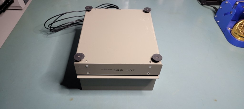

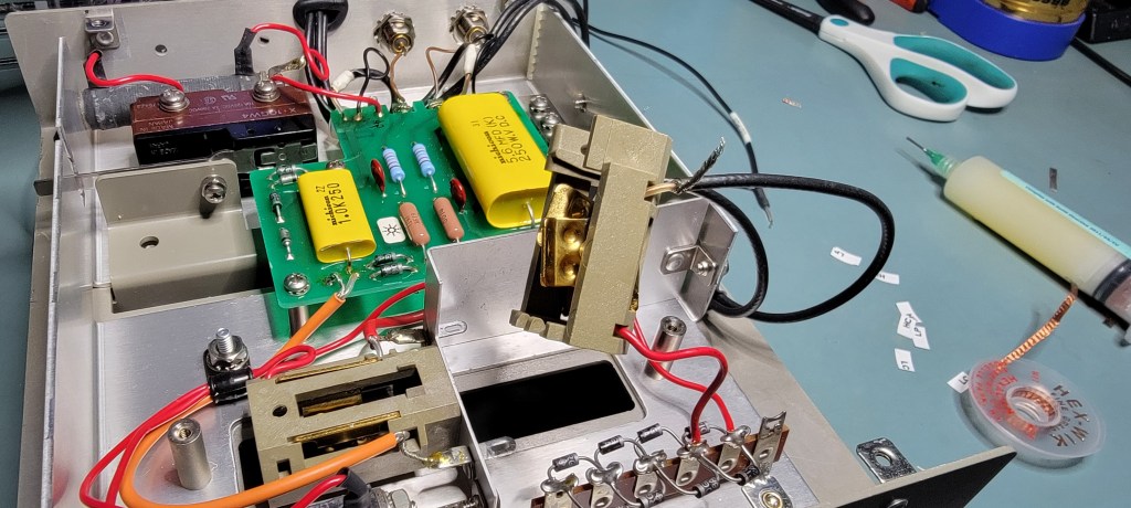
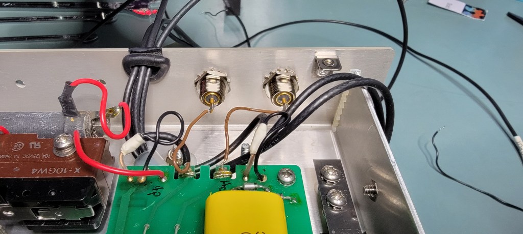
Right away we can get a glimpse of the interesting bits.

Looks like some modifications were made by the previous owner however. Note that there is some strategically placed electrical tape on the safety interlock switch and DUT discharge mechanism…

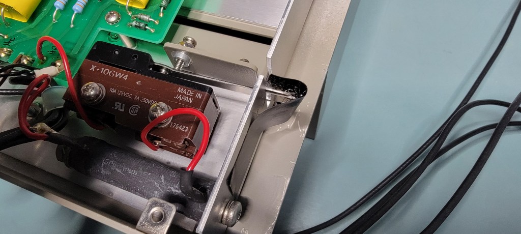
Safety third! Well, to be fair, if it was operating at low (< 30) DC bias in the previous application then the risk of electrocution is low. I suppose the last guy found the interlock and discharge mechanism annoying. What I don’t understand is why the coax connections across the low terminals were chopped and moved back to the diode array which blocks DC on the low side and keeps discharges flowing in one direction.
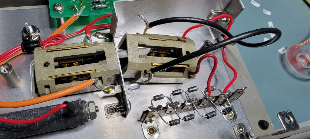
Maybe my guy thought his DUT would fail short and the high side of the DC bias would pass to the low terminals? Weird. To preserve measurement integrity, it is important that the coax transmission line carrying our AC measurement signal terminate as closely as possible to the DUT (which Agilent had originally intended…)


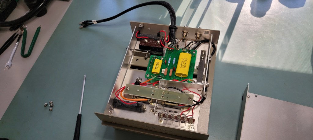
I set about undoing the previous mods and restoring it to factory condition.
Let me tell you, cutting and stripping the coax to the exact right length was no simple task. Neither was soldering it onto the DUT connection bars with most of the fixture still assembled. I also ended up replacing the rear BNC bulkhead connectors for the DC bias input and monitor, as one of them got smashed in shipping. Of course, the finest Pomona connectors were the only choice…
I chose to terminate the 4 terminal pair coax into SMC connectors as I already had an HP branded 16048B 4 BNC adapter for use with my LCR meter. This way, I get some extra cable length and don’t need to age the front panel connectors on my meter for a fixture swap to my Kelvin clips (which I also wired to connect to the 16048B with SMC connectors).

Now that the fixture is restored to it’s (mostly) original condition, we are ready to do some tests. Before I attached it to my LCR meter, I made sure to apply the DC bias first (up to 200 volts) and make sure that the DC did not pass to any of the SMC connectors which connect to the LCR meter itself. I also verified that the interlock was operating correctly (no DC at the DUT when opened).
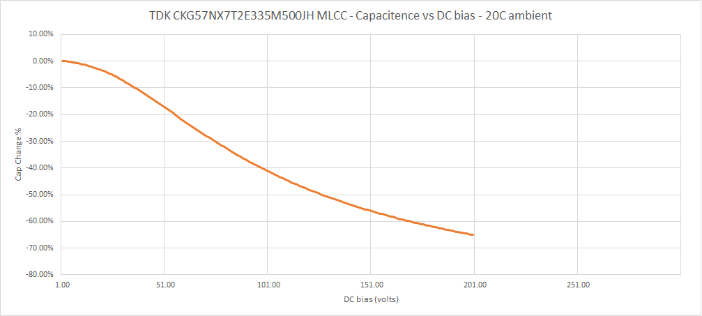
Time to test a part! I chose to test a 250 volt, 3.3uF rated X7R ceramic capacitor, TDK part #CKG57NX7T2E335M500JH. I use high voltage caps like these often in my nixie tube power supply designs, and always wondered what kind of capacitance they had left at 180-200 volts. An important property of ceramic capacitors to remember is that the actual capacitance decreases significantly as the DC bias across the cap increases.
I had to begin by soldering some short leads to my the cap (since it is a surface mount part and the 16065A is for through-hole parts).

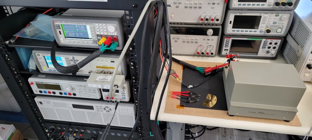
I hooked the DC bias input and monitor up to Channel 2 of my B2902A SMU, which could be programmed to source voltages accurately up to the 200 volt limit of the fixture.
The 4 terminal pair SMC connectors were then attached to the 16048B fixture, which I plugged into my E4980AL LCR meter. I did perform open and short compensation on the fixture before inserting the capacitor.
Then, pop the DUT into the new fixture!

Hardware is all set!
As for software, I used Keysight Benchvue to program the SMU and LCR meter to work in sequence to apply the DC bias, make an LCR measurement, increase the bias by +1 volt, make another LCR measurement.
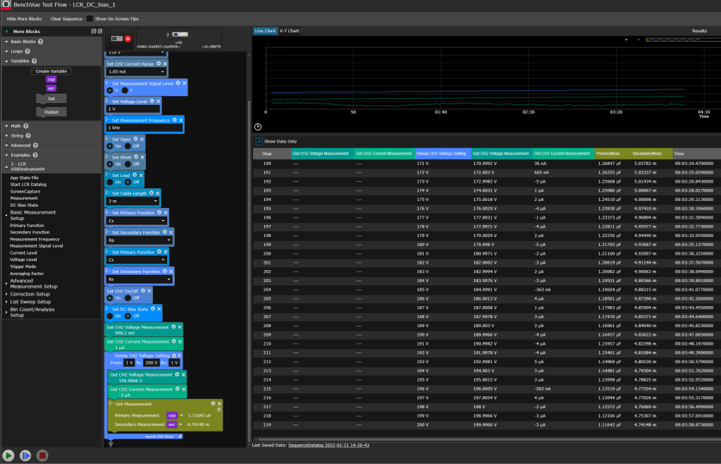
I have never done this in Keysight’s BenchVue software and it took me about 10 minutes to figure it out. My hat is off to the BenchVue team for creating a great GUI for multi-instrument control. Sure, I could’ve written it in Python using SCPI and PyVisa, but I paid for BenchVue a while ago and the time saved is worth it in my opinion for quickie tests like this.
I measured the cap from a 1 to 200VDC bias in 1 second intervals with a single measurement at each point. Here is my plot of DC bias vs Capacitance up to 200 volts:
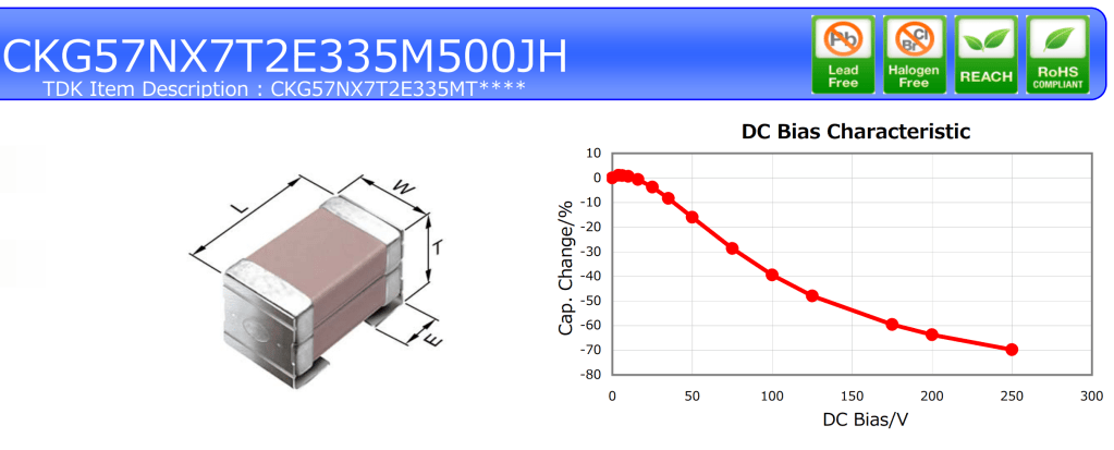
And here is the one from the TDK datasheet:
Not bad! Looks like this project was a success and a nice addition to the LCR fixture toolbox. Can’t have enough fixtures…
