
Since I’ve been on the hunt for more RF tools, I stumbled across an N9344C for auction online at the recommendation of a friend.
Auction info was extremely limited; no blurb to suggest that the analyzer worked or did not work. I took a chance and decided to bid on it; if unrecoverable, at least it would be a valuable learning experience to disassemble and have a look inside.
From the pictures, it was obvious that the analyzer was also missing a knob and came with no power adapter. So I ordered a Keysight 0950-5825 AC adapter and an N9330-47400 knob from their online parts store in anticipation.
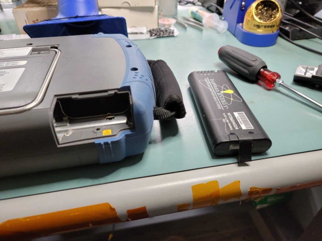
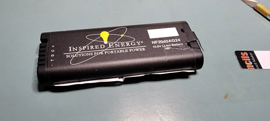
Fast forward a few days after winning the auction, and the analyzer shows up at my door. Being a field instrument, it is a little dirty and scuffed as expected, but nothing outwardly unusual to suggest physical damage. Well, minus a big crack in the battery pack, which was probably dropped when removed from the instrument.

So to test initially, I fired up the AC6081 programmable AC supply, and plugged in the power adapter into the AC supply and the spectrum analyzer. As soon as I turned the AC output on, I see the power adapter trying to start but going into a hiccup protection mode.
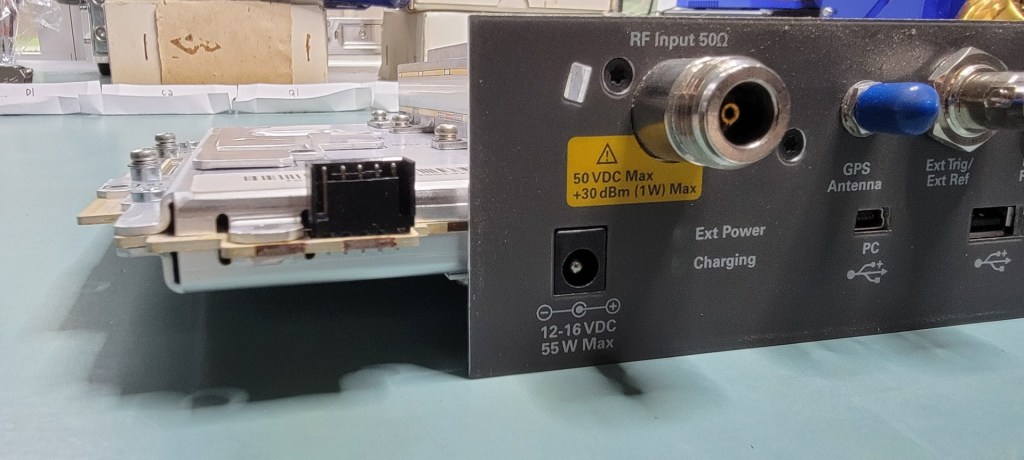
Given that the adapter is brand new, something must be wrong at the DC input of the analyzer. I take out my multimeter and measure across the DC barrel jack on the N9344C; it reads 2 ohms! There is a short somewhere along the DC input. So we must open the instrument and follow the power input path.

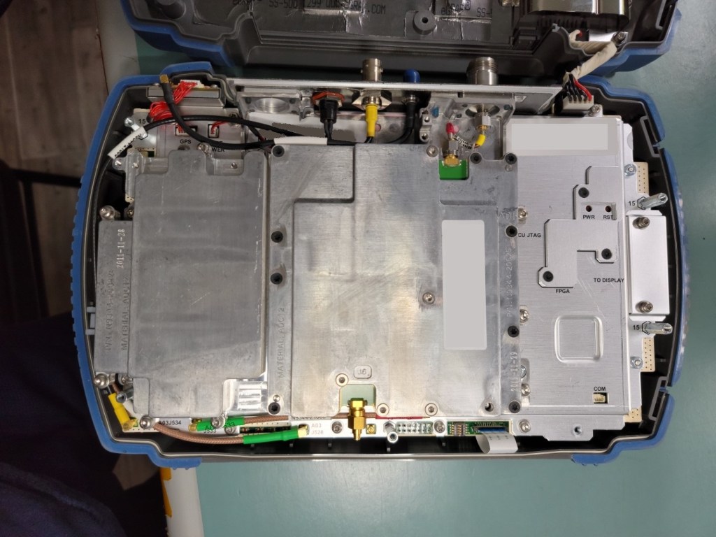
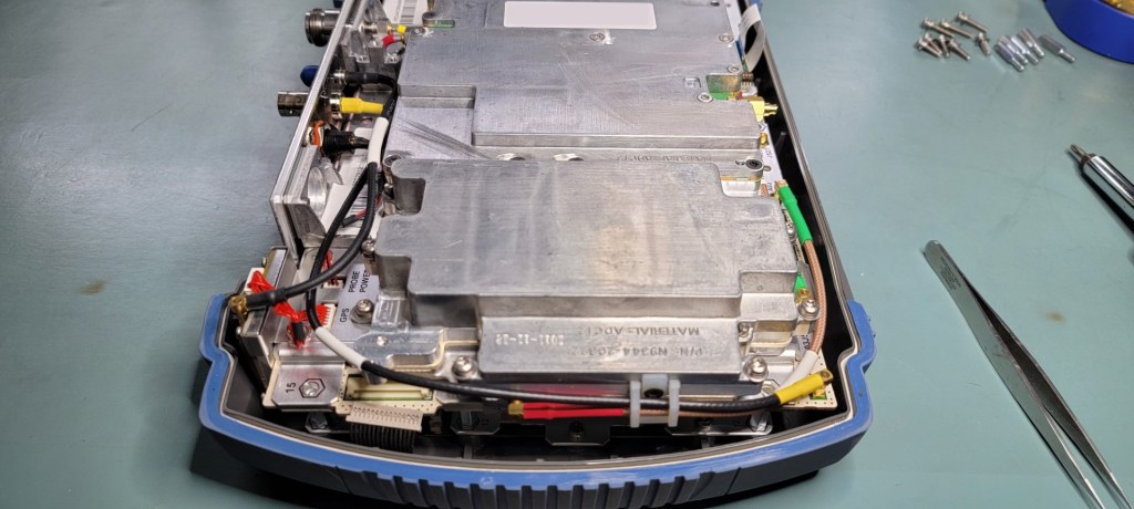
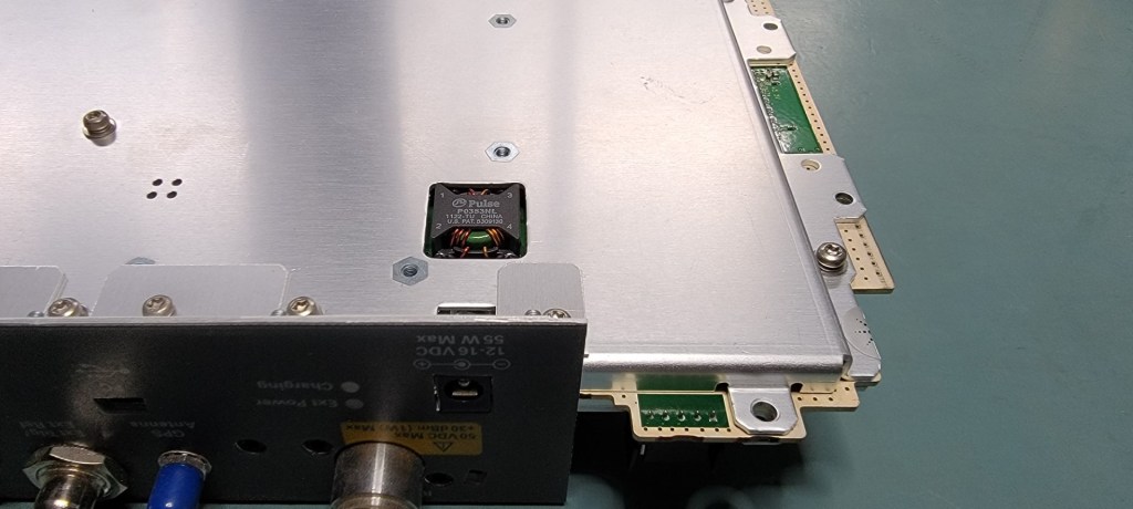
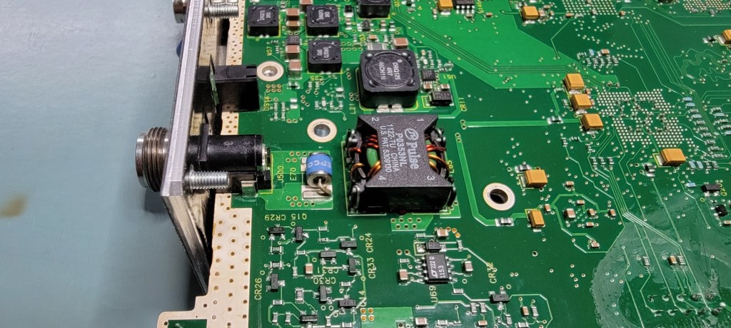
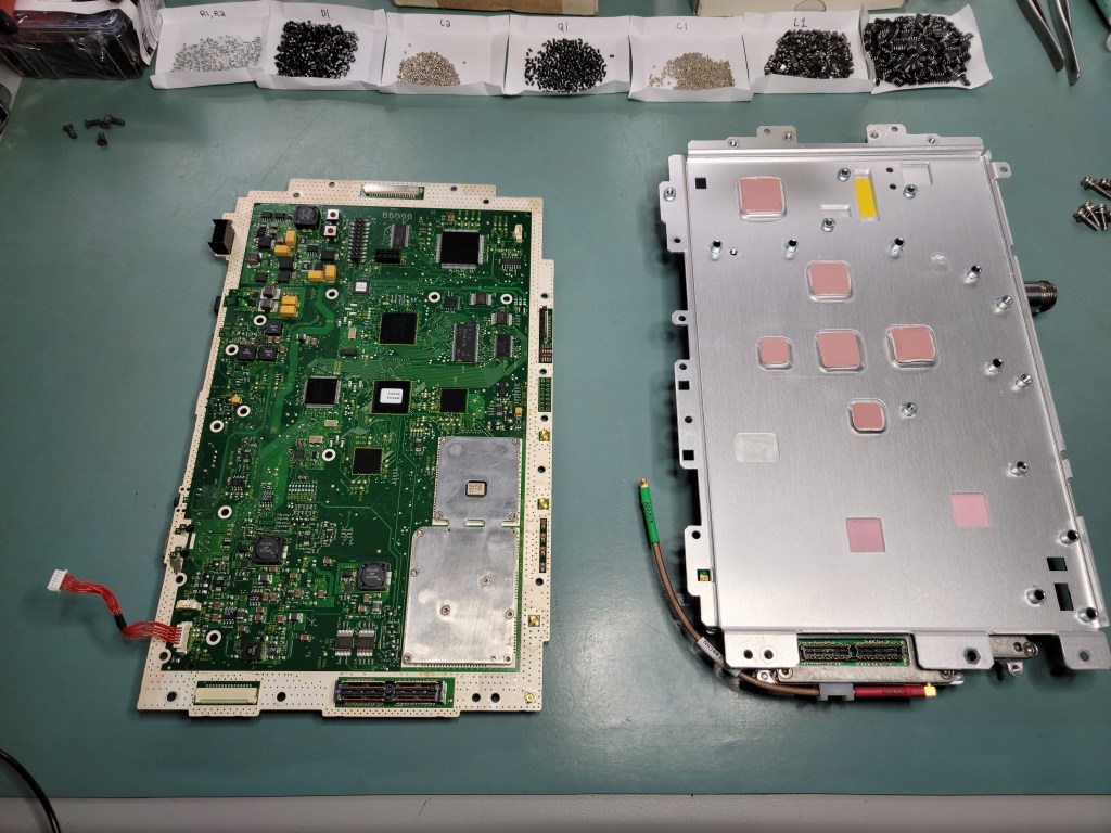
More details pics (always good to take plenty of pictures – you will thank yourself when it’s time to reassemble!)


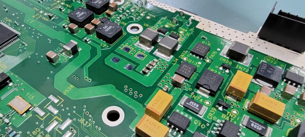
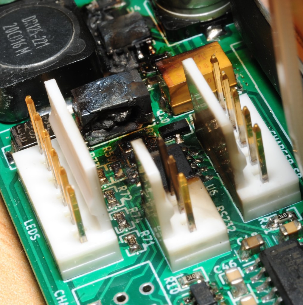
Narrowing in on the main digital board where the DC input is located:

In order to find the short, I decide to attach a programmable DC power supply to the input and start by applying very low current and voltage. Using my HT-301 thermal camera, I will look at the board near the barrel jack and keep incrementing the current until I can just see the heat being dissipated by the short.
I set the supply to 2 volts, 100 milliamps, and crank it up 100 milliamps at a time. At 300 milliamps, the offending component begins to stand out:

Turns out to be the usual suspect, a solid tantalum capacitor! Thankfully it didn’t explode in the usual “tantalum tantrum” fashion.
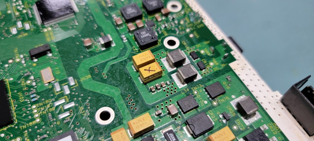
Since this tant appears to be serving as bulk capacitance across the DC input, we can remove it and partially reassemble the analyzer just to see if the instrument resumes working. Removing the bad cap reveals a rupture in the case wall that likely happened at the moment of failure.

Partially reassembling the boards and powering on, the moment of truth!
It lives! The instrument boots normally and does not show any errors.
After re-disassembling, a thorough cleaning inside and out plus one digikey order later, we are ready to replace the bad capacitor (and the one next to it, just in case) and button this analyzer up.

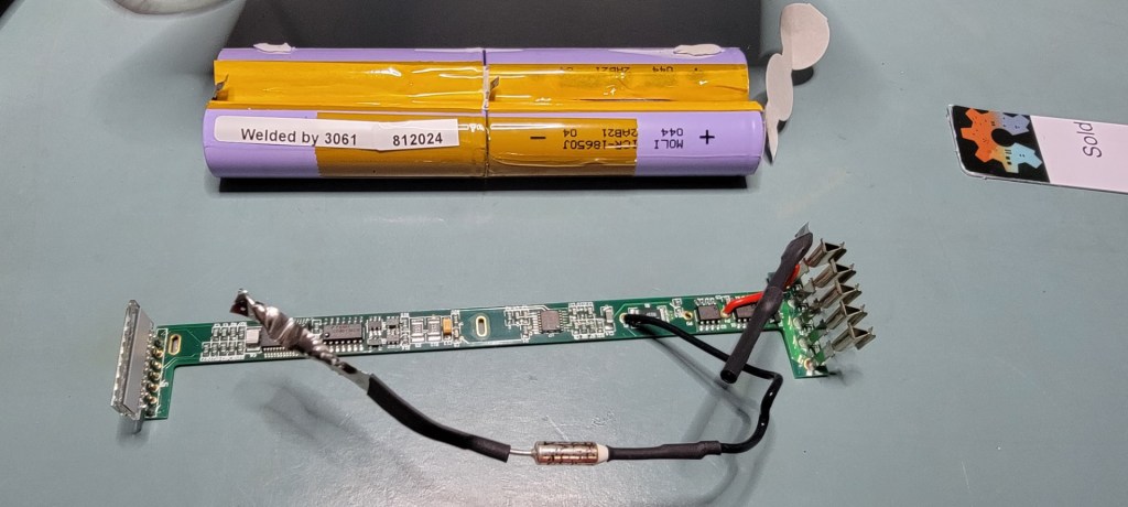
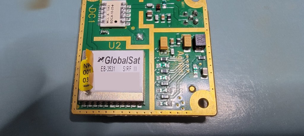
Out of curiosity, I had a look inside the damaged battery pack and GPS module before putting the instrument back together.


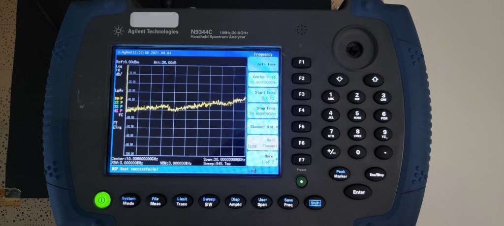
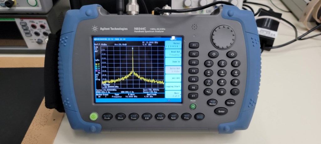
After a careful reassembly, we have ourselves a nice working spectrum analyzer! Measuring a 10MHz tone from a GPSDO I built (designed by Nick Sayer, project page: https://hackaday.io/project/6872-gps-disciplined-xcxo )

Overall, I am thankful that luck was on my side and the repair was simple. Tantalum capacitors usually fail with quite an explosion, burning through the host PCB in the process. A new digital board for the N9344C would have been $4,500 USD from Keysight!
Example of a failed short – then exploded – solid tantalum capacitor.
Source: http://www.mattmillman.com/mc34063-a-tough-lesson/
With this handy (no pun intended) analyzer added to our toolbox, I’ve got some more repairs lined up on a few broken high end RF instruments. Stay tuned!
