
Based on sharing and discussing my 20 watt design with the nixie tube community, there is a desire for an even higher power high voltage supply. Several neon enthusiasts are building displays with many large tubes, and a single power supply solution is viewed as preferable.
In an attempt to satisfy this niche requirement and challenge myself, I set out to double the available power of my previous 20 watt version. If you recall from my thermal diagnosis of the original design, the MOSFET was by far the “limiting” component. My first attempt in increasing the power was to incorporate a larger transistor.
In striving for higher power levels, I also did some preliminary calculations and realized that I would need a higher value inductor. By increasing available inductance, the switching frequency also needed to change (get lower) in order to accommodate the longer RL time constant associated with charging and discharging the inductor. I decided to go from a 560μH inductor to 1mH based on the output power goal, as well as lowering the switching frequency from ~70 kHz to approximatly ~32 kHz.
I hooked up my 100 watt load resistor (860 ohms), to simulate a fixed 200 milliamp load at 180 volts. On first power-up (12 volts in) the supply turned on for a second, then quit!
I then realized “It’s not gonna be that easy!”
Keep in mind what I am trying to do: make a single inductor based boost converter than can step up 12 volts to 180 volts at 200 milliamps out. That is a 15:1 boost ratio, and at the power level I’m aiming for, the design becomes nontrivial very quickly. There is only so much energy you can wring out of an inductor at a given voltage and charge/discharge time!
Now, I know what you’re thinking: “Why don’t you use a transformer?”
Because I want to make this design work, that’s why. Transformers are the obvious choice for this kind of application: you can easily achieve the step-up voltage due to the primary to secondary ratio. In addition, you can use a low-voltage transistor as the input and output are galvanically isolated.
Instead of brushing aside the design, I view this project as a good learning experience to see just how much I could optimize this boost converter through a combination of instrumented investigation and plain old experimentation.

The first place to start was by cranking up the input voltage to see if 40 watts was even possible out of this design. I raised the power supply voltage to 24 and sure enough, it runs without a hitch. The TPS40211 is a wide input range controller (4.5 ~ 52 volts), and all of my passives are still within spec at 24 volts.
I took some thermal images to assess heat dissipation. Again, through good thermal management practices such as via stitching and using copper pours as heatsinks, the hottest components were (as expected), the inductor and the diode which did not exceed 81°C.
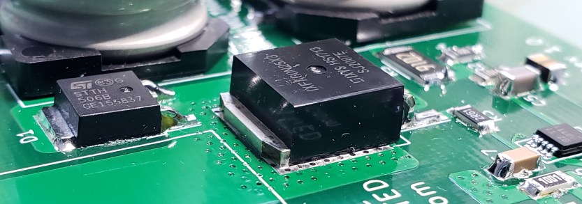
Now, it was time to probe out a few points on the circuit to see what was really going on. I hooked up my scope to the MOSFET gate and the inductor output, both relative to the common system ground.

I began by capturing these signals at different input voltages. I wanted to see how the controller responded to dropping input voltage, to see where limits in the system arise. I found that the lowest operating voltage the supply could handle at 200 milliamps out was around 14 volts… close, but not quite 12!
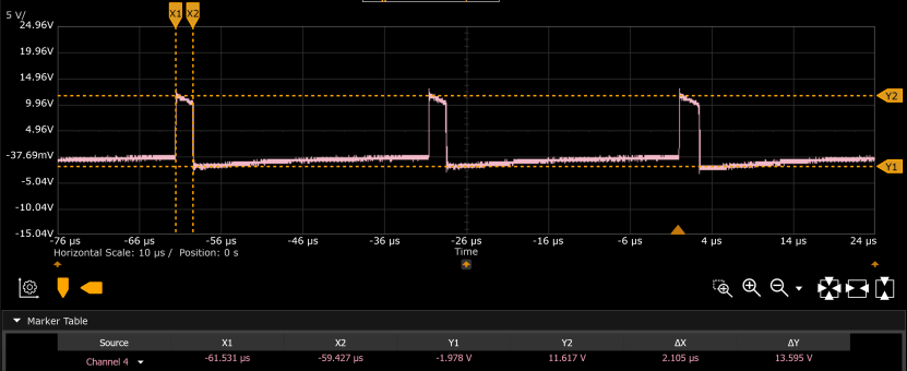
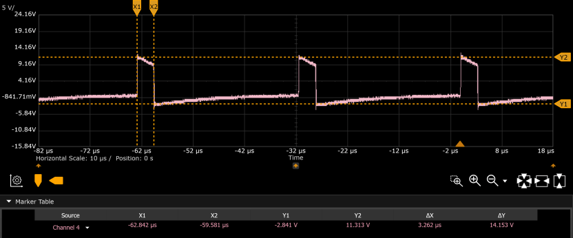
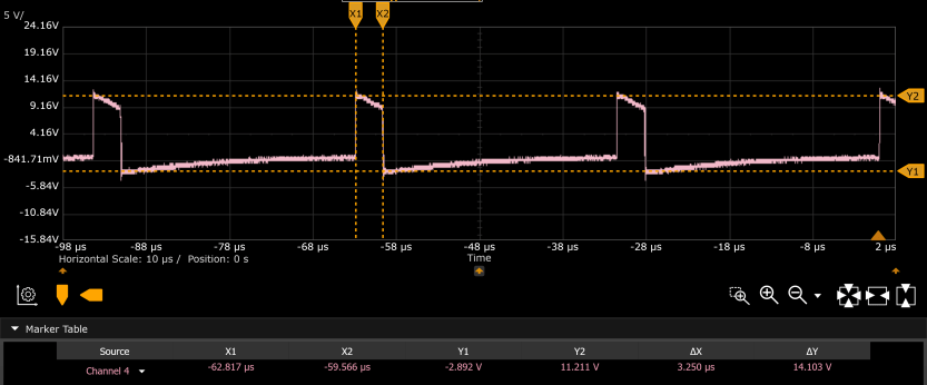
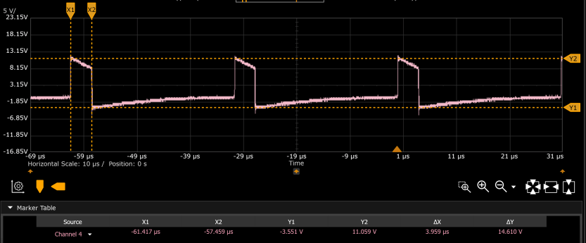
It is clear that as the input voltage drops, the inductor charging duty cycle increases. Consequentially, the discharge time also decreases, as you can see by the ΔX marker in the above waveform analyses. Another point of observation is the consistency of ΔY with with input voltage. If you recall, this measurement is in the potential difference between system ground and inductor output. At 24 volts in, the peak-to-peak inductor voltage between charged and discharged is about 14.6 volts. Compare that to 13.6 peak-to-peak at 14 volts in. A 1 volt drop across the inductor at 10 volts drop across the input signifies that for the 1mH inductor, 14 volts is the target charge level for 200 milliamps at the output. Once the input drops below 14, increasing duty cycle does nothing as the inductor is saturated and simply cannot provide more energy.
The next step will be to increase inductance and conduct the same battery of tests. As energy stored in the inductor is directly proportional to inductance, hopefully this change enables the supply to operate at 12 volts for full 200 milliamp output!
