
Quick update. Since my last post regarding the design of a 20 watt high voltage boost converter, I have churned out another design based on the TPS40211 controller using the same transistor and diode combination. Using a smaller inductor and proportionately less output capacitance, I have fashioned a 10 watt rated design for use with the MOD-SIX 7971 clock.
The schematic is as follows:

Bill of materials: (Note 1 change, see bottom of article)
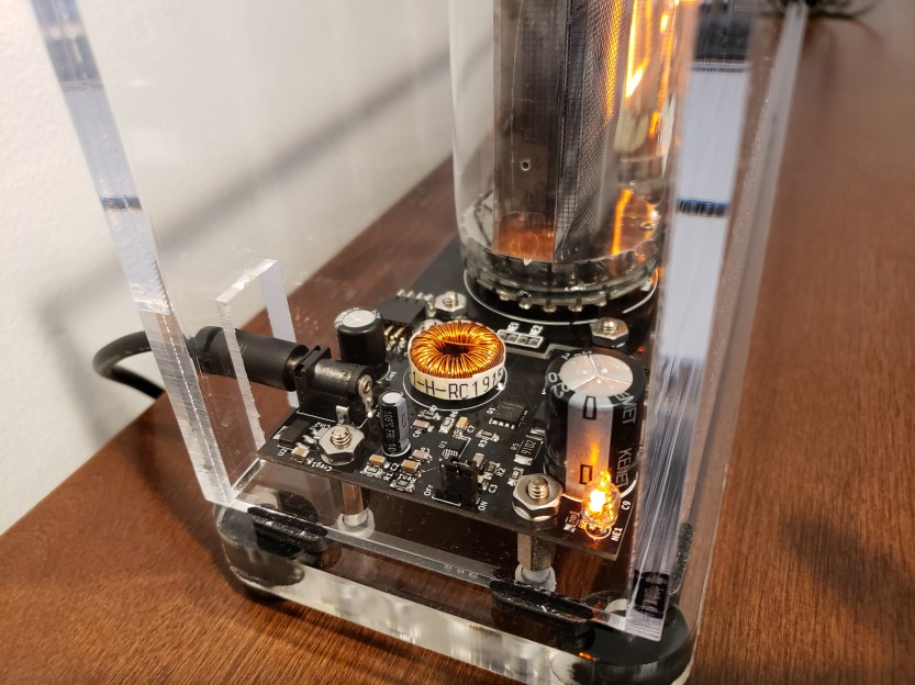
Performance was comparable to the previous design. Efficiency at a 48 milliamp load was 78%, which is was a few percent lower than the 20 watt design due to the 8 volt linear regulator included in this design for powering the MOD-SIX logic. Thermal management was also quite satisfactory, with the feedback resistor reaching a maximum of 47°C and the switching MOSFET getting no hotter than 75°C at the same 48 milliamp load, in free air. Peak-to-peak output ripple was about 2.2 volts, resulting in 1.2% ripple under load. What I enjoy the most is that the unit is absolutely silent under all operating conditions; the same cannot be said for others, which occasionally emit irritating squeaks under transient loads.
Behold, the final product!


Also, an interesting point of comparison: the most analogous off-the-shelf DC-DC converter I can find is the XP Power FS02-12. It is a 10 watt, 12 volt to 200 volt DC-DC converter, which costs about $150 per unit from Digikey. Efficiency is quoted as “75% – 85% typical”, with <6% ripple. Compared to the power supply I designed, which costs at most (if you only bought 1-2 of each component) ~$28 in parts and $9 per board (again, in low quantities of 5), for a total of $37, with virtually equal performance to the XP Power. If produced in quantity, cost could easily drop below $30 per unit. Another obvious benefit to owning a design is tailoring it to the intended application, as I did here.
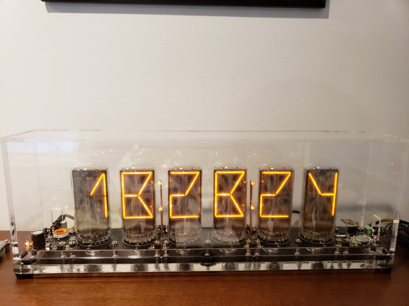
This project has been another fantastic learning experience. Plus, I can appreciate it every time I gaze upon this beautiful nixie clock!
DISCLAIMER: The information provided here is for educational purposes. You assume the risk of correctly assembling and safely handling any electronics, especially high voltage electronics as shown here which can cause harmful or lethal electric shock, and/or equipment/property damage.
You can find artwork (gerber files) here: PCBway Shared: 10 watt 12V to 180V nixie power supply for MOD-SIX clock
Update 9/8/2019:
The current sense resistor R7 (shown as 40mΩ) should be slightly higher in value, to limit the output and heat generation of the supply at the rated 10 watt power level. Recommended values are between 55-70mΩ. The lower the value, the more current the supply will put out before going into over-current protection. If you plan on running at the higher end of the power spectrum, plan to provide additional heat-sinking for the MOSFET.
A high power (40 watt) nixie supply is currently in the works, based on my 20 watt version but with a larger MOSFET and improved layout. Stay tuned!

Hey I’m a MOD SIX owner and was wondering if what advantage this might provide over the existing MODSIX PSU
LikeLike
Hi JT,
Thanks for your comment. There are several advantages which a dedicated design brings to the MOD SIX.
The first is sustainability. Currently, the MOD SIX uses either an APD S10-180 or the Tayloredge high voltage power supply. Both are made by third parties who are not major retailers, so distribution of these units is limited. Additionally, neither is user serviceable. If it fails, good luck finding another unless you happen to have a stash of them. By having a power supply design which uses off-the-shelf parts, the MOD SIX electrical design is now 100% source-able through common vendors like Digikey and Mouser.
The second advantage is low noise. Switch mode power supplies can produce audible noise, usually from the inductor or ceramic output capacitors. This design is completely silent due to the switching frequency and careful selection of output caps. The same cannot be said for some of the existing HV supplies used in the mod six.
I am in regular contact with the man behind the mod six electrical design. He explained to me that when the clock was first designed (years ago), cheap and powerful boost controllers like the TPS40211 did not exist, and neither did MOSFETs with specs like you will find now. The technology was limited and made the trouble of designing a power supply greater than the benefit. The game is completely changed today, where off-the-shelf components have tremendous capability at a reasonable cost. Technology related to switch mode power supplies in particular has evolved incredibly fast as they are presently used in countless applications.
LikeLike
Thats Awesome!!
Thanks for the explanation and your work, Maybe it will make it into the next MODSIX revision 😀
JT
LikeLike