

UPDATE 11/5/2023: See my latest project for a newer, feature rich PWM speed control circuit with tachometer readout, rotary encoder interface, and more:
Let’s start with a small and simple project. If you own a desktop computer, it probably has several fans inside for cooling. Some of these fans run at a fixed speed. Others can be controlled to run at different speeds. If you wanted to use a fan outside of your computer, how would you replicate the same digital signals used to control these types of fans?
First, a small preface to how and why we use digital circuits to control DC motors:
Before transistor technology existed, virtually all DC motors were brushed. This means that commutation, or the transfer of current between windings in a rotating motor, was accomplished using a mechanical brush. The brush itself was usually made from carbon, which was soft so it wore into shape as the motor spun to form a good circuit. The brush is pressed against a circular stack of metal slots, called the commutator. As the motor spins, the current is transferred around to each coil on the rotating armature, keeping the motor spinning by changing the magnetic field:
Image 1: Brushed 3-phase DC motor (courtesy of Renesas Electronics Corporation)

Image 2: Brushed DC motor closeup; brush, commutator, windings

With the advent of low cost and high power transistors, commutation can also be done with electronics. This type of motor technology is known as brushless. The mechanical commutator is completely eliminated, and the motor is controlled purely by switching electronics:
Image 3: Brushless 3-phase DC motor (courtesy of Renesas Electronics Corporation)

While it might seem simpler to stick with a mechanical brushed motor, many integrated circuits are so inexpensive that all computer fans used today use power brushless motors.
Image 4: 3-phase brushless motor electronic speed controller (ESC)
(courtesy of Benjamin Vedder [vedder.se] )

In low power applications (including low power PC fans without speed control), commutation is done with a simple hall-effect circuit that detects the position of the spinning fan rotor and flips a switch (the transistor) to change the magnetic field. Many of these fans are two phase and do not have a PWM control option.
For those of us interested in high power fans, we need a way to control them. There are many fans with 40 watt + power ratings, and they almost always need to be throttled.
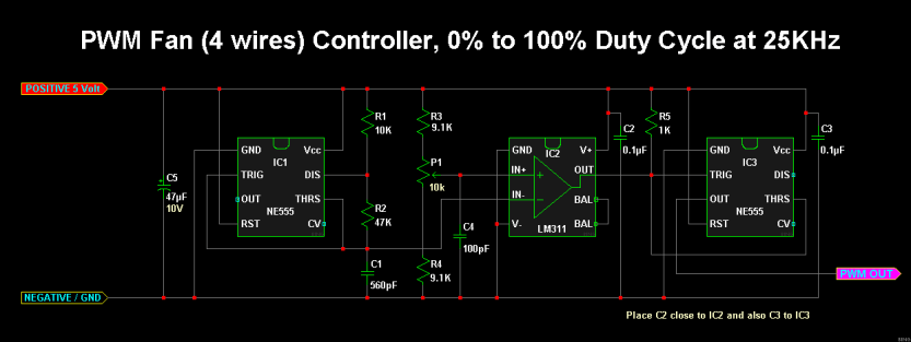
Fortunately, because brushless motors are digital, many fan manufacturers add logic to the motor controller circuit (similar to the speed controller in image 4). The most popular protocol by far is a 25 kHz PWM signal to change fan speed. All you have to do is send a square wave at this frequency to the fan, and the duty cycle will determine the fan speed. That is precisely what the circuit below will do:
(image from overclockers.com)
Without further adieu: I devised a small PCB to contain this circuit in an organized way, and added a voltage regulator to make life easier. Now, all you have to do is plug in your fan, your power supply, and a potentiometer, and you can finally tame your unwieldy high power fans! If you have a fan that needs a different frequency, changing C1 will change the output frequency generated to suit your needs. You can calculate different resistor/capacitor combinations with the 555 timer here: 555 astable frequency calculator

Here is a link to OSH Park, where you can order this very circuit to put together yourself:
OshPark Printed Circuit Boards: PWM Fan board
Here is a Google Drive folder containing a bill of materials (BOM), KiCad and Gerber files, and pictures of the first test circuit including a bench test:
Google Drive: PWM fan controller
I hope you found this article useful! This circuit is a simple yet practical introduction to the ubiquitous 555 timer and was key in developing my skills as a well rounded engineer. Please feel free to download the board files and change things around in your favorite EDA. I highly recommend KiCad as it is free and relatively user friendly (in my opinion).
Added 12/31/2018:
Second board assembled with different voltage regulator: LM2936HVMAX-5.0/NOPB
This will allow you to use up to 60 volts on the input to the board. Perfect for high power 48 volt fans! These fans usually use the same 25 kHz driving frequency as their lower voltage PWM modulated counterparts.


Disclaimer: No guarantees expressed or implied. The information presented here is for educational use. You are responsible for safely and correctly assembling this open source project. I am not liable for any damages or injures to equipment or persons as a result of improper handling procedures, incorrect assembly, or any form of misuse or negligence. Please ensure you exercise proper safety precautions as defined by NFPA 70 and NFPA 70E when assembling and using electronics.

Thanks for sharing this!
Are you able to share the full schematic that goes along with the board?
LikeLike
Hi Joseph. Thanks for checking out the site! I did not lay out the board with a schematic, but it is exactly the schematic that in the article with a voltage regulator. That’s it!
LikeLike
Hey Kevin. You did a really good job of the PCB. Did you happen to see the version that uses a single 556 package in place of the two 555s? It is even more compact, but functionally it is the exact same circuit. Sadly many of the images on the thread are no longer live, but I uploaded the schematic for you here: https://imagizer.imageshack.com/img922/8712/EzVwMe.png
Credit always to Victor Bing who is the wizard responsible for this fantastic electronic design!
LikeLike