A site dedicated to projects I do for fun. Hopefully you get a kick out of it!
Posted on
Vision Engineering Lynx microscope – C073 LED ring light custom power supply
Necessity is the mother of invention, and microscopes need a lot of light to properly illuminate a subject.
Vision Engineering is one of the premier brands in the industrial microscope market. Their most popular product is likely the Mantis, which can be seen in many industries from medical to electronic device manufacturing.
Late model Mantis Elite – image source: tequipment.net
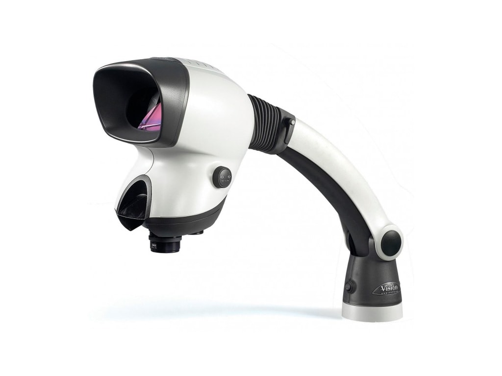
While not as ubiquitous as the Mantis, the higher performance Lynx series of microscopes from VE offer a significant advantage in terms of user comfort when compared to the traditional binocular microscope. This lies in the “Dynascope” technology. To quote the VE webpage for the Lynx:
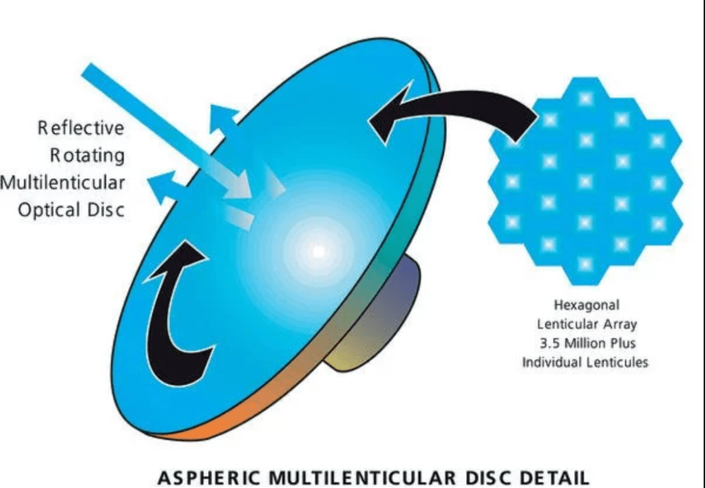
“Dynascope has redefined the science of microscopy, overcoming the physical limitations of conventional microscopes to help laboratories and workshops improve quality and productivity. At its heart, there is a multi-lenticular disc which incorporates more than 3.5 million individual lenses, or ‘lenticules’, each just a few microns in diameter. The multi‐lenticular disk spins at high speed to merge the millions of individual optical paths into a high‐clarity, high contrast image”
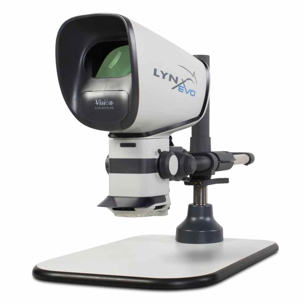
Late model Lynx EVO – image source: medicalexpo.com
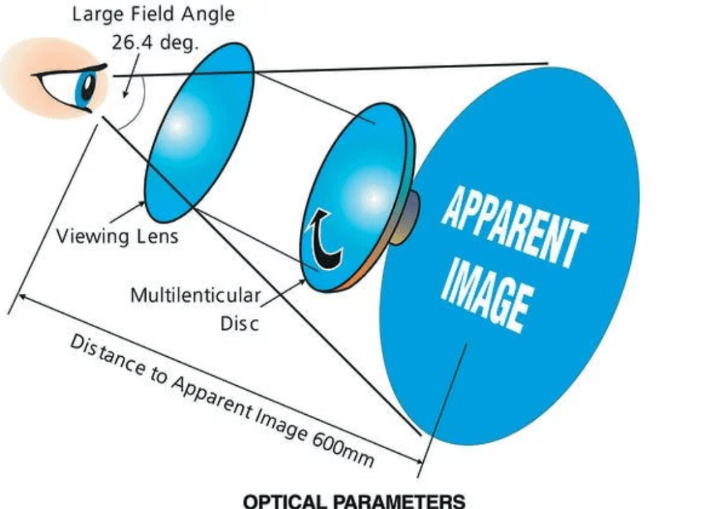
The main advantage of the Dynascope effect is an extremely wide field of view for the operator; it enables a true stereo microscope experience without any eyepieces. The following pictograms from Chris Browne of Vision Engineering illustrate the apparent field of view and optical setup of a typical Dynascope stereo microscope.
I am not paid by or affiliated with Vision Engineering in any way. I have used their microscopes from the 1st generation Mantis (with halogen lighting) up to the latest model Lynx Evo. There are good reasons why professionals choose these products for magnified inspection; optical quality and operator comfort being two of the dominant ones.
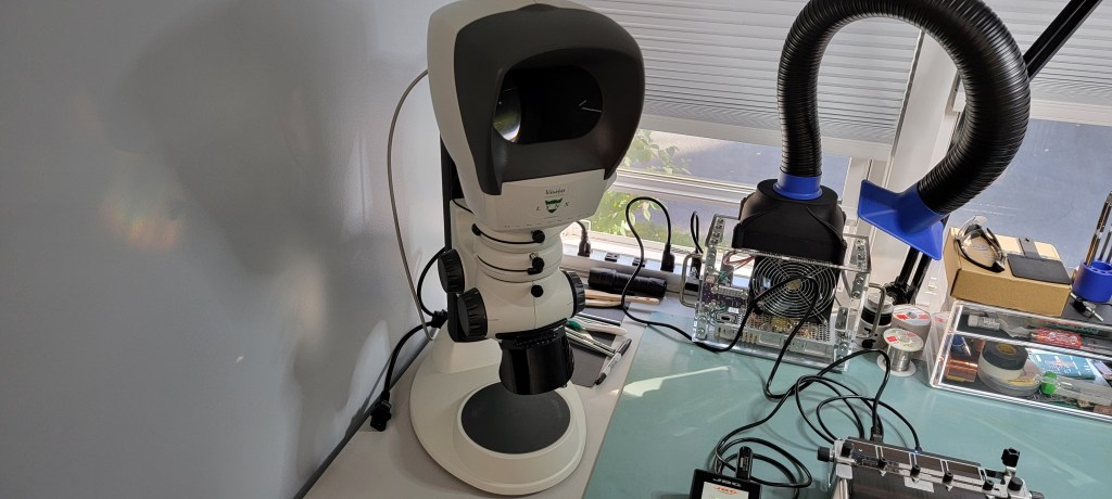
For someone such as myself who does a fair bit of soldering on modern PCBAs, having a good microscope is crucial for inspection. After a year or so of browsing eBay, I finally stumbled on a mint condition, mid-generation Lynx. The unit included a compact bench stand with built-in head power supply and halogen base illumination.
The next piece of the puzzle was to get the correct light source. Vision engineering made both halogen and LED ring illuminators which mount around the main objective lens to provide top lighting on the subject.
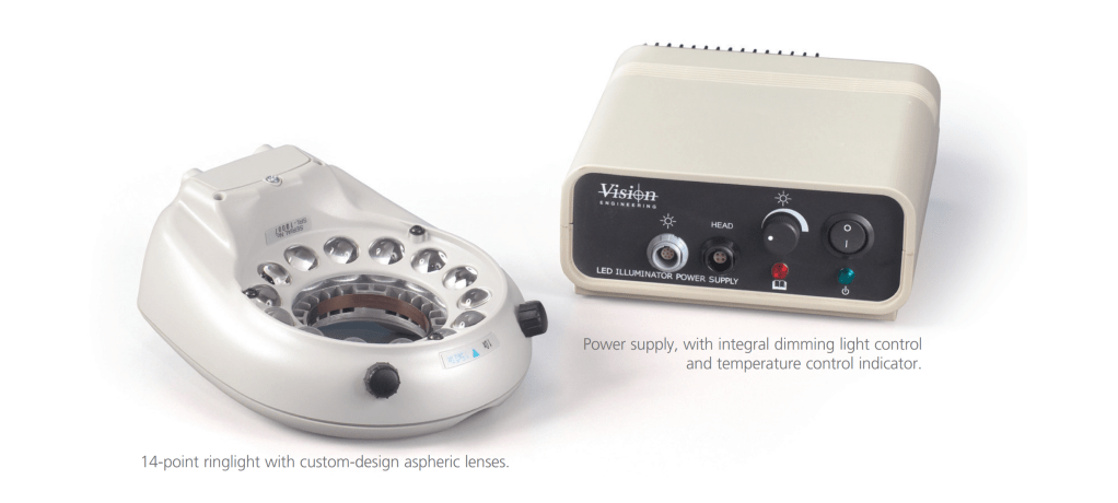
My preference is of course LED; it is far more energy efficient than incandescent lighting which also translates to less noise and heat in normal operation. The correct LED illuminator for this generation of Lynx is the C-073 ring light, which pairs with a custom Vision Engineering power supply.
Image of C-073 14 point LED illuminator with matching power supply from VE brochure.
I spotted a C-073 illuminator on eBay not too long after buying the microscope, so I bought that right away as well. The only problem was that I could not find a corresponding power supply!
Well, how difficult is it to drive the LEDs on the head? I was confident suitable LED drivers ICs could be had and implemented readily with the abundance of semiconductor lighting applications today.
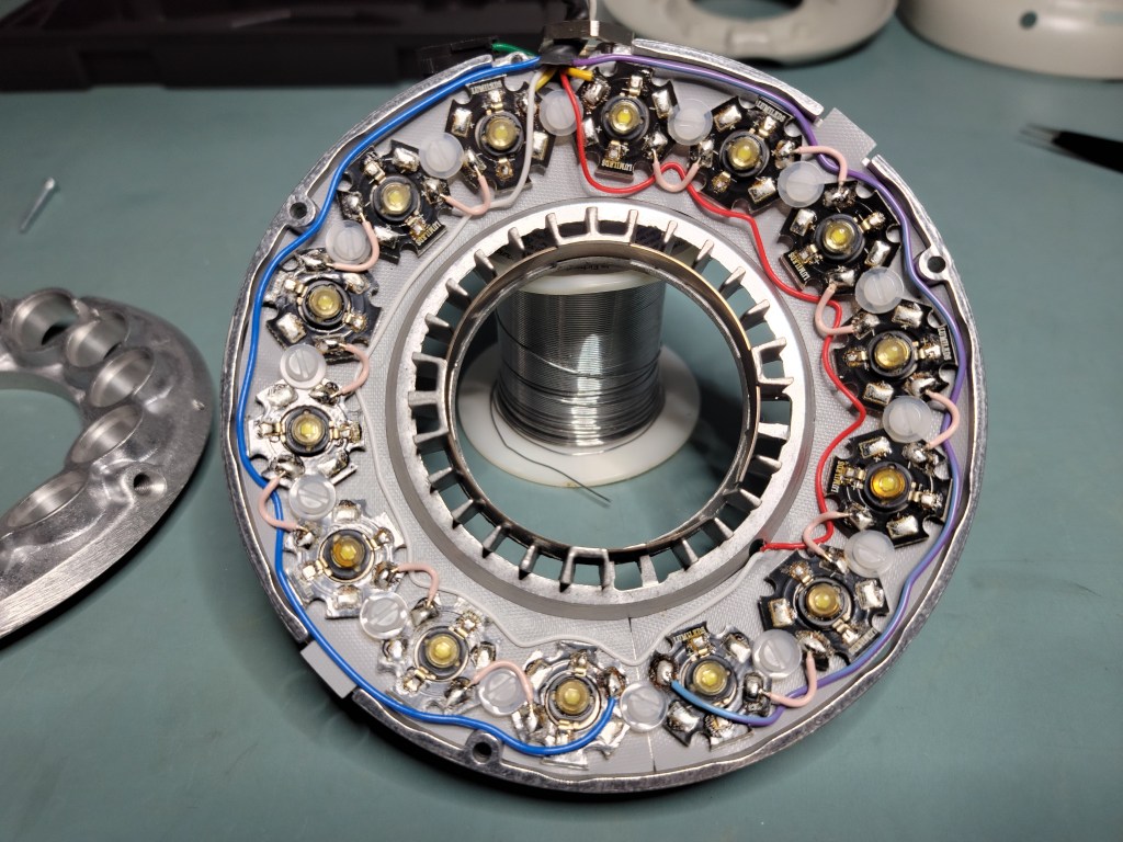
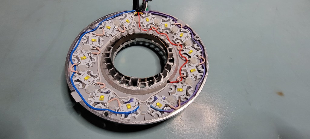
The C-073 light is a 14 point illuminator. There are 14 individual LEDs underneath each lens:
The LEDs are wired in 2 strings of 7 LEDs in series. This keeps the required series voltage for each group to a relatively safe level (30-ish volts). In addition to 2 pairs of LED power connections, there is a PT100 thermocouple also installed in the C-073 heatsink to keep an eye on temperature. The last device in this illuminator assembly is a 12 volt DC fan which draws air in from the center of the heatsink to keep things cool.
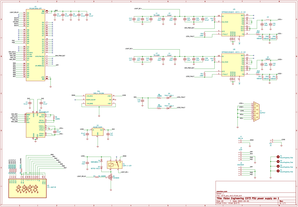
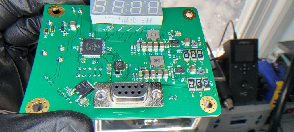
After some searching on Digikey and Mouser for a suitable LED driver IC, I stumbled on the MPM6010-AEC1. It is a synchronous current mode LED driver which supports PWM dimming. To achieve the current power needed for all 14 points, I decided to use one for each string of 7 LEDs.
Sticking to the PIC16 line of MCUs, I elected to use the PIC16F1946/47, which has plenty of IO and flash on board. In addition to driving the DC power relay and generating the PWM for dimming, I wanted to have the PIC display the temperature of the PT100 in real time. In order to do this relatively accurately, I decided to use a MAX31865 RTD-to-digital IC which incorporates many RTD measurement features into a single chip.
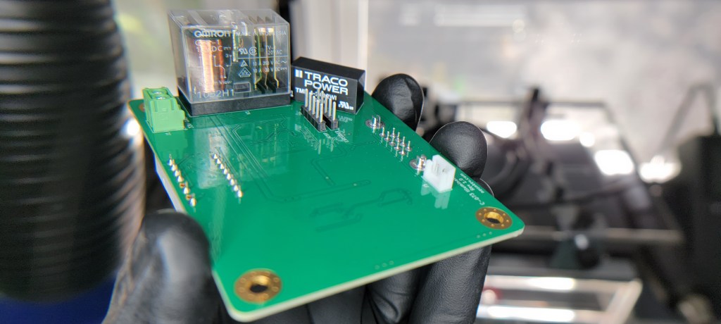
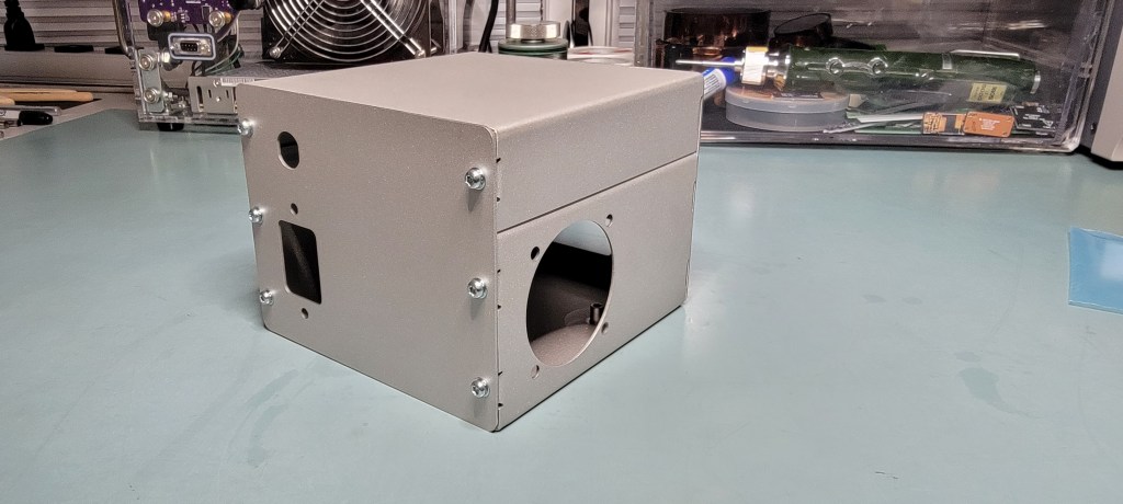
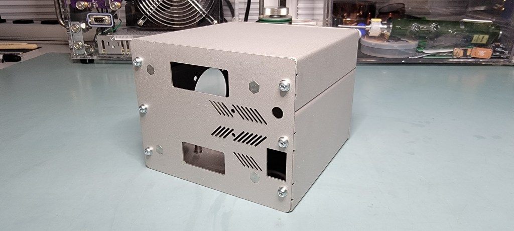
Of course, I can’t just have a free-hanging board if this is to be a useful tool on my workbench. I set about designing a sheet metal enclosure house the board and the main power supply I chose (Traco TPI 180-136A-M). The enclosure is also to house a fan for active cooling of the main electronics. While temperatures didn’t prove to be terrible excessive during testing without cooling; a little airflow can’t hurt.
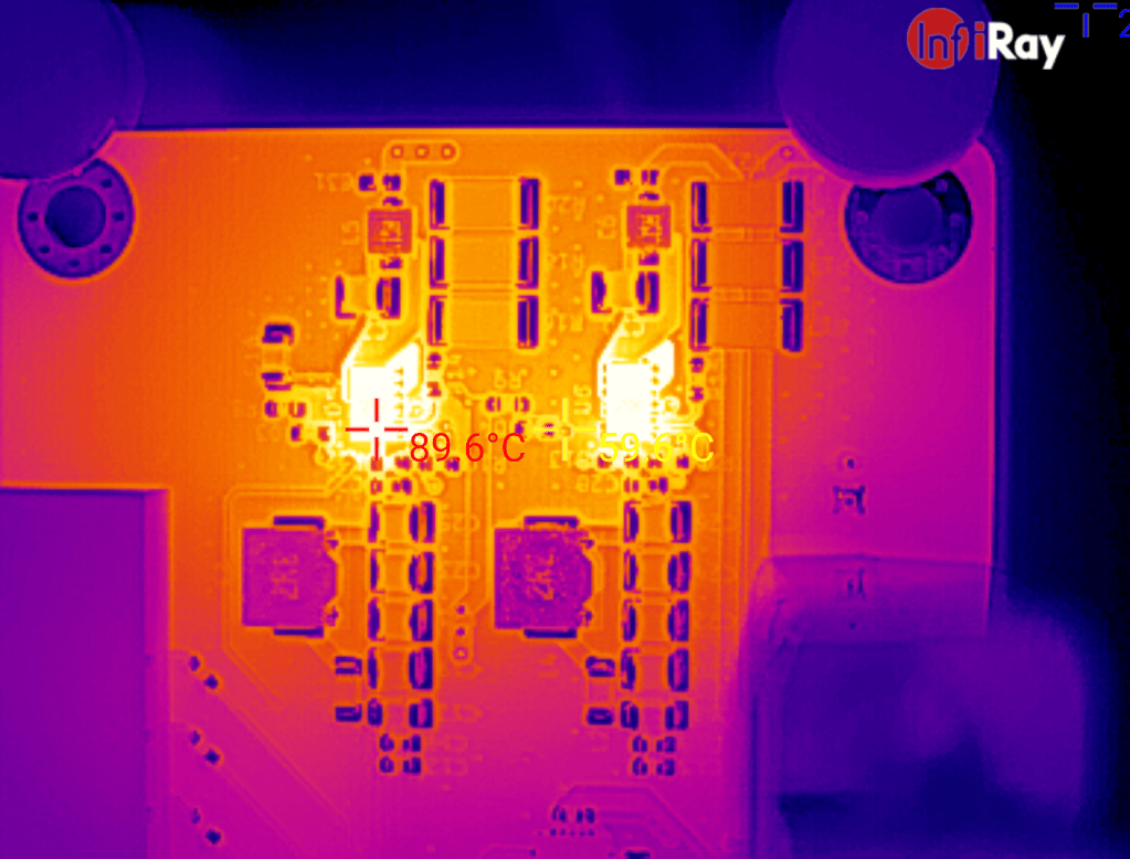
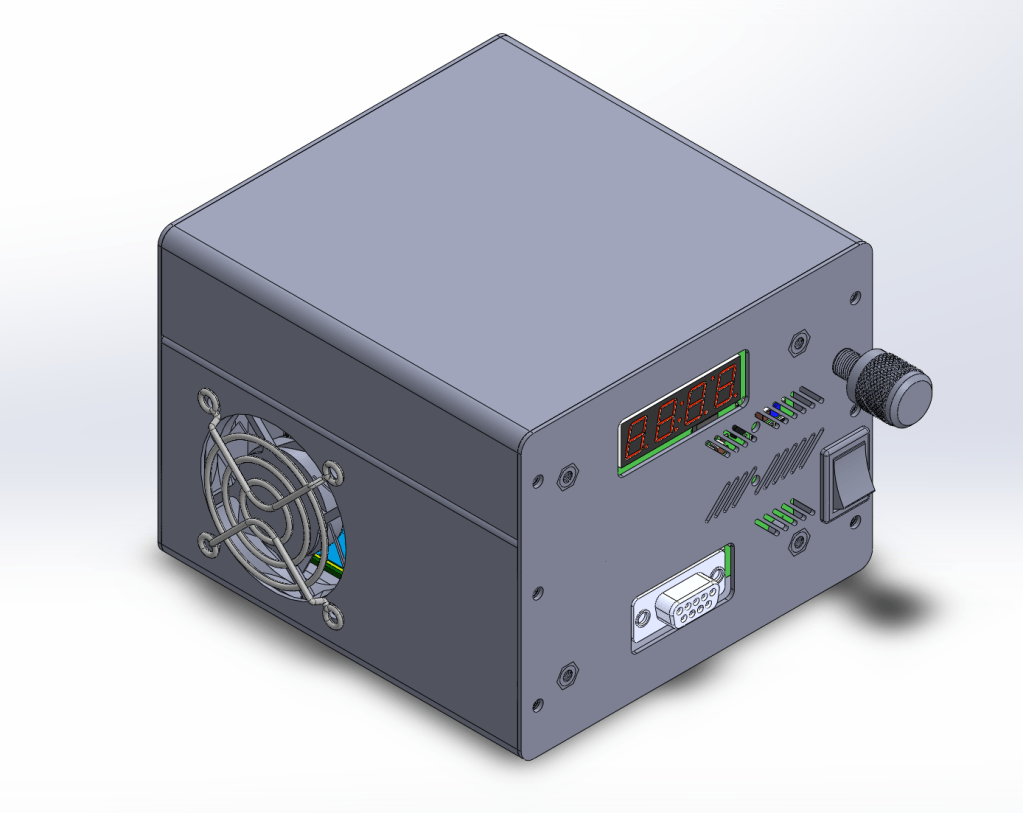
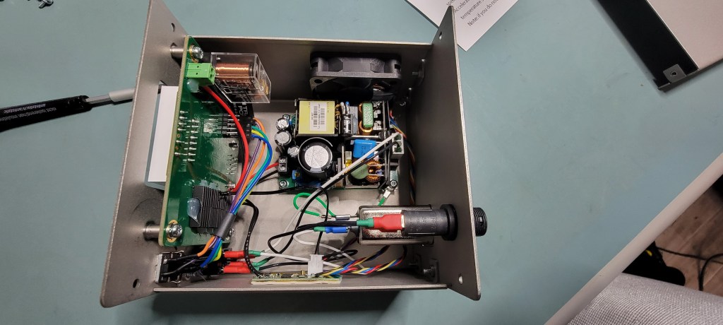
Peak long-duration temperatures of MPM6010 at full brightness, no active cooling.Custom designed sheet metal enclosure – bead blasted stainless steel with press fit threaded PEM insertsFinal implementation using Rev1 board.
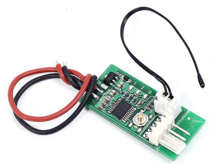
In order to keep the fans quiet in the LED head and power supply case, I ended up using 4-wire fans (Delta AUC0512DB-AF00) with this handy little temperature speed controller module (eBay link):
One other improvement I made was to retrofit the C-073 with the latest Luxeon-star LEDs (Luxeon Star website link). The new LEDs I used are part number SP-01-W5: Cool White (5650K) Rebel ES LED on a SinkPAD-II 20mm Star Base – 235 lm @ 700mA.
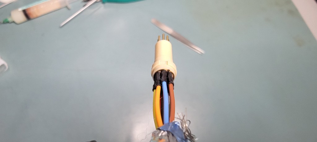
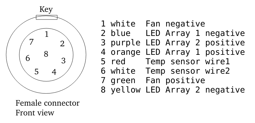
The only other materials needed were to build a wiring harness between the C-073 head and my power supply, which uses a standard DB9 connector. The C-073 head requires mating ODU part #S21M07-P08MFD0-657S (Mouser link).
I used West Penn Wire 3271 for the cable, which is an 8 conductor 22 gauge shielded cable (eBay link). A good quality, generic male DB9 connector assembly will do for the power supply side of things.
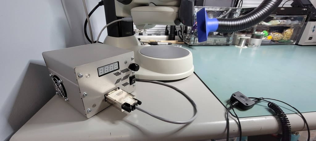
After a fair bit of firmware development (namely writing a library for the MAX chip!) the project works. I wouldn’t call the results perfect, but Rev 1 never is. It works and has been doing so for a year. I could pump more time and effort into refining it, but I have a working microscope and more pressing projects.
Rev 1, working 1 year later
Here is a quick demo of the current result:
Project files (gerbers, BOM, firmware) are available for download below (MIT License applicable to all contents):